Designing the Energy System for Off-Grid Woodworking at The Barn on White Run
When I returned back home from the microhydro-electric workshop at SEI I had a fairly clear idea about the logistical and technical requirements for my system. There were several integrated elements.

1. A body of running water. Check. While the flow was variable, the creek on our property had never gone dry in recent memory, so I figured all was well. The hydrology is so unusual around here with all the porous limestone and aquifers you can hardly throw a rock without hitting some kind of running water. This county has between 400-600 creeks, some of which are seasonal.

2. A way to get that water contained and downhill. As a practical matter this meant using a PVC pipeline to capture all the water I could as high as possible to exploit the inherent energy contained in running water. Given our hydrology and topography I figured I could get somewhere between 30-50 gallons per minute from an elevation about 100’ higher than the power plant.
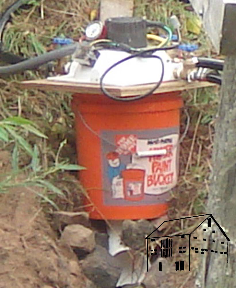
3. A mechanical device at the bottom of the pipe to generate power from the force of the water jet coming out of the pipe. The evident answer based on the technical literature was a “Pelton wheel” turbine, which is basically a tiny(!) Ferris wheel which is turned by the water jet. The whole “machine” fits on top of a 5-gallon bucket! My turbine is 4” in diameter and the 48-volt heavy-duty truck alternator attached to it can produce more than a kilowatt of power if the water flow is enough. Mostly I get somewhere between 200-500 watts continuous output.
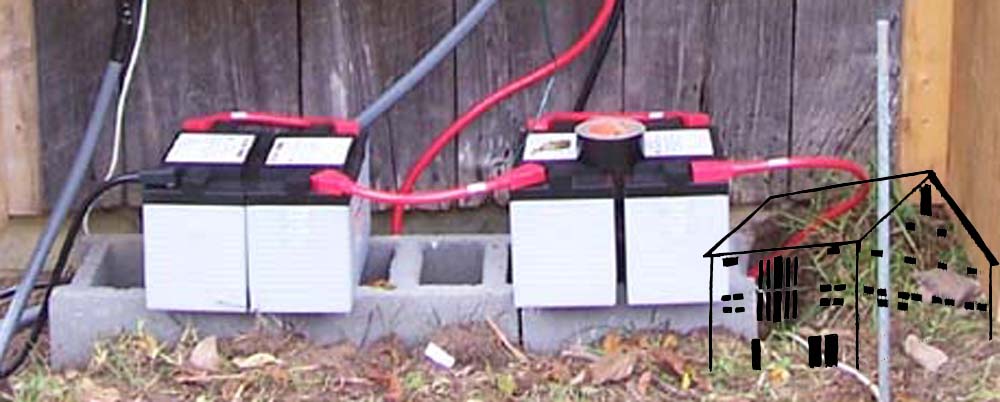
4. A method to store the power being created by the turbine. Giant truck batteries were the answer to the problem. I started out with four big deep-cycle batteries, the kind used for diesel truck engines.
5. A sophisticated system of electronic devices to control the electrical output from the turbine, to feed it into the batteries and dump the excess when they got full.

6. A high-power inverter system to transform the DC current from the turbine, and then feed the power to wherever I wanted it to go. The tail end of this system was standard wiring throughout The Barn. The “business end” was a matched pair of 48v input-to-110v output inverters in parallel, so I could have 220v in The Barn if I need it. In between was a 330’line of 6/3 cable fed through a shielded flex conduit.
At this point let me invoke the Schwarz Disclaimer — all of the products I cite in this series of articles are devices which I paid for in full, and get no benefit or consideration from their manufacturers nor distributors.
Up next — Building the System

Join the Conversation!