
The conceptual foundation of this saw is the ability to rotate the saw blade within the saw frame. When noodling the design and fabricating this hardware element I considered many options before settling on something nearly identical to Roubo’s.

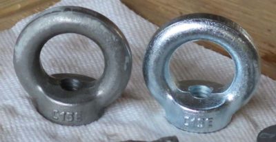
I ordered a variety of of sizes and configurations of eyebolts from McMaster-Carr to play with.

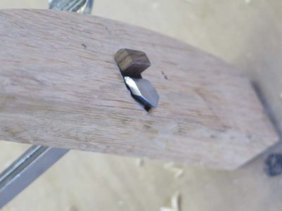
The eye large enough to accommodate or incorporate the 1/2″ cylindrical rod for affixing the blade was simply too huge for the proportion to work properly. The eye of the correct proportion was made for a threaded rod way too small for the 1/2″ wide blade. In the end I took that smaller eye and drilled and tapped it for the cylinder rod of the right size.

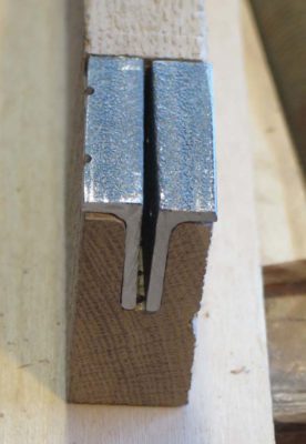
I split the eye bolt with my jeweler’s saw and a #10 blade. I then drilled the cross-holes through which the blade could be attached to this split rod.
One of the last things I did before assembling the whole saw was to de-zinc the hardware parts by soaking them in a citric acid solution (about 2 tsp/pint of water). As soon as the mild acid began to work on the zinc the solution got cloudy. I had to monitor the progress and removed the hardware when I had gone far enough.

I assembled everything to make sure it fit but I did not give the saw a test drive since I did not have the saw blade that would be used for it.

I disassembled it and shipped it off to Wisconsin. I cannot wait to get a production prototype back to give it workout.

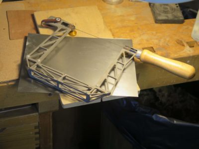
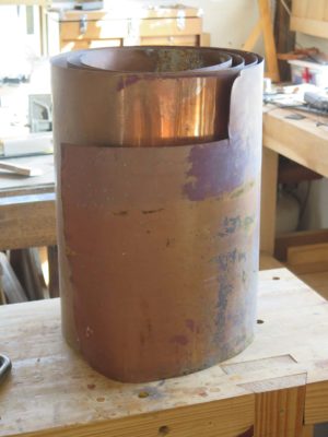
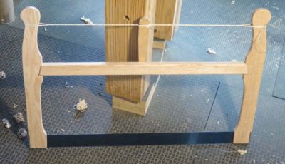
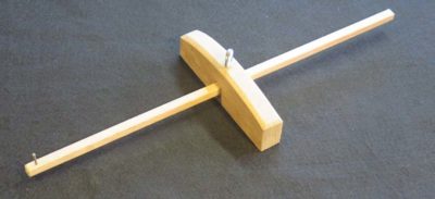
With the Roubo Joinery Saw prototype winging its way to Wisconsin I turned my attention to, well, Roubo’s “turning” saw from Plate 12, Figure 5. I used the identical design for the overall bow for the Joinery Saw, but there were more than enough twists and turns along the road to make it interesting.
The term “turning saw” has two particular meanings. First, the saw plate is narrow enough so that it could be turned as it worked its way through the workpiece. Second, the plate itself could be turned in the bow, enhancing the capabilities of the tool.
I began from the premise used in the Joinery Saw, namely that I would be trying to replicate Roubo as closely as possible based on his illustrations and verbal descriptions. As before I used white oak for the wooden elements. For the saw plate I just used a broken band saw blade since Bad Axe has not yet begun to develop theirs.
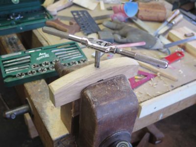
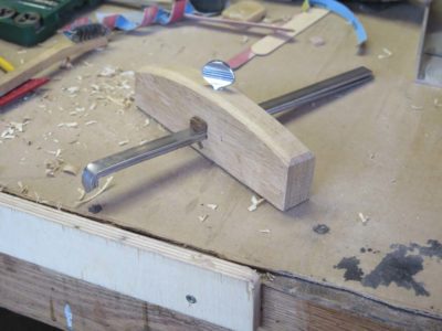
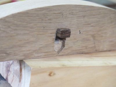
Thus the two crucial differences were the housing at the end of the bow arms through which the round spilt post passed, and the split post itself.
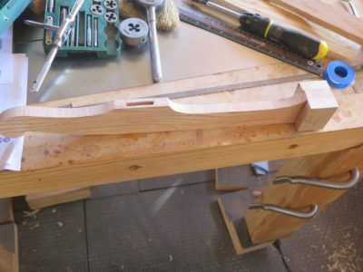
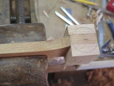
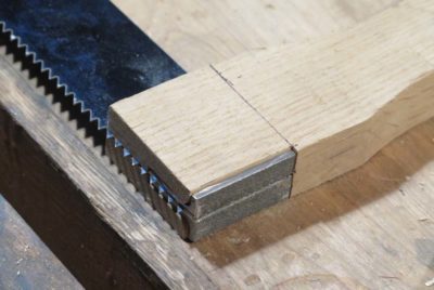
The bulbous end block was the simpler of the two problems to solve. I glued scrap blocks in place, laid out the bulb, and shaped it to the design. Drilling the hole for the post was simple enough.
Next time – the split post and related fittings.

I think that when creating a production-worthy Plate 12, Figure 3 prototype at the request of Mark Harrell of Bad Axe Tools, I spent the most time and creative energy in working out the problem of retaining the saw plate in the bow saw arms.


My first effort two years ago worked well enough for one guy making one saw, but it was IMHO insufficient for any kind of production run. The amount of work necessary to excavate the base of the wooden arm in order to receive this particular two-piece stirrup configuration made this option a non-starter.
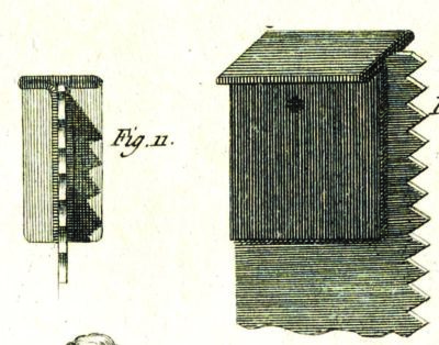
Plus, like the configuration of my original Art Nouveau-ish bow saw frame it bore little resemblance to Roubo’s illustration. His description and illustrations clearly represent a folded “T” shaped fitting-with-pin for holding the saw plate in a slot at the bottom end of the arm. So, that is the direction I headed towards. At this point my only fundamental deviation from Roubo was that Mark’s saw plate had two holes rather than Roubo’s one.
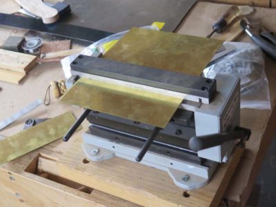
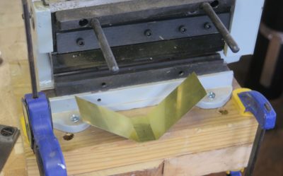
I ordered some 1/32″ steel sheet, unfortunately it did not come in narrow configurations so I wound up sawing it by hand until I had pieces that would fit into my little shear/brake. Once I had the strips in-hand I started the process of figuring out how to accomplish this tricky series of bends. Fortunately I had my sweet little shear/brake from Micro-Mark to help me. Sort of.
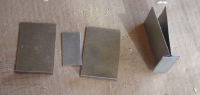
I found that the brake’s bending was so crisp that the steel snapped off at that point. Actually, what happened is that I could bend crisp 90-degree corners then had to spread them in order to bend the next set of corners, then bend the original corners back. That’s when they snapped. I eventually did figure out how to get it done (see below).

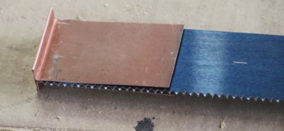
After the steel sheet gave me trouble, before I figured out the solution I tried some .030 copper flashing I had sitting under the stairs in my hardware store. It cut like butter with my engraver’s hook and folded in the brake without a hitch. (I swear I do not know why Photoshop and WordPress cannot play nice with each other!)
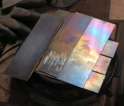
Since copper worked so nicely but was pretty soft I decided to try something halfway in between, .030 brass. Unlike the copper it was really stiff so I annealed it on my hotplate before trying to bend it.
By this time I had hit on the solution to the earlier problem that caused the first steel stirrup to snap. Instead of making the first bends to 90 degrees then bending them open, I bent them only enough to establish the corner.
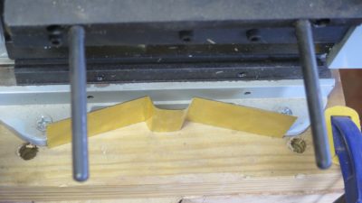
This allowed me to use the brake for the second bend. Then by hand I could fold the unit closed with a hammer and cold chisel until it was in the “T” configuration.
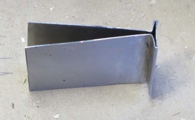
I worked this system in all three materials and found the solution to be darned near perfect.
I drilled out the stirrup and arm to match the holes in the saw plate and held the entire unit together with binding posts. I apologize for not taking a picture of this assembly all by itself.
With the entire stirrup now passing through the bottom of the saw arm there was virtually no joinery involved; just make the slot for the stirrup and plate, widen it a bit, and slip it all together. Inserting the binding posts completed the assembly of the saw and all it needed for working was the windlass and cord. I used a much smaller windlass bar than my earlier one, about 1/3 of the weight of that one.
I took pictures, dismantled it and shipped it off to Wisconsin.
Now, on to Roubo’s Turning Saw.
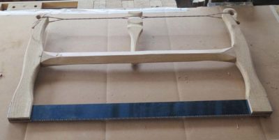
Aside from the fact that my first effort in producing a joinery bowsaw based on the Bad Axe saw plate didn’t look like Roubo’s, only one of several features rendering this prototype useless to Mark in designing a production run, it was way too heavy at over six pounds. That extra weight was fine for when the saw was engaged but sure was a nuisance when trying to maneuver it in between cuts.
So, I went back to the starting point and recut all of the wooden elements to both be slimmer and look like the saw Roubo illustrated in Plate 12, Figure 3. In the end the only dimension that remained unchanged as the length of the saw plate. Everything else was thinned, widened, thickened, or narrowed as I felt necessary.
The resulting weight reduction of almost 25% was noticeable immediately.
I literally enlarged this image to almost life size when creating the template. Again I used some of my stash of clear white oak left over from the fabrication of the Studley bench top for that exhibit five (!) years ago.
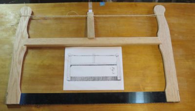
The cutting and configuration was straightforward in the gross sense, but I spent a lot of time getting the template for the end pieces just so, reflecting the illustration Roubo created for the tool. This is a tricky proposition, as the proportions and details of tools are not always perfect (see Plate !! for confirmation) but it had to be closer than the Art Nouveau-ish version I created for the first one. Once I was happy with the shape and proportions of the arms I made a solid template from which I could make as many tracings as I wanted.
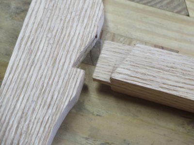
Of particular interest to me was the juxtaposition of the stretcher to the end arms; the only way the saw made sense in the flesh was to have the stretcher be notably thicker than the arms. So that is how I made those three pieces. In the end I made the stretcher about 1-1/16″ and the arms 3/4″. I fussed over this detail for a couple weeks.
Notching the arms to receive the stretcher was also an issue as I had to make sure the strength of the arms was not compromised by too large a mortise. I accomplished this by making sure the loose mortise-and-tenon assembly was quite thin, just a bit over a quarter inch and shallow at a half inch. Since the joint’s only purpose was to keep the pieces in alignment that worked out just fine. All the stress was in compression so the tighter the windlass was turned the more solid the bow structure became. Unless, of course, it broke. Hence my fussing.
But that was not the worst of it as noodling and fabricating the stirrups for the end of the saw plate was way more problematic.
Stay tuned.
Some time ago I was asked by Mark Harrell of Bad Axe to build production-able prototype versions of the bow saws Roubo featured in L’Art du Menuisier, Plate 12, Figures 3&5. He was considering adding them to their product line and I was delighted to collaborate with him as I would be with any tool producer.
My first effort two years ago resulted in some success but some failure, so in recent weeks I have been trying to extract more of the former and expunge the latter. My first attempt yielded a prototype that was unsatisfactory in the important aspects of the tool; 1) it was way too heavy, 2) did not look anything like what Roubo described and illustrated, and 3) had plate fittings wholely unsuited for manufacturing (yes, I know I spell wholely different that the dictionary; the dictionary is wrong). So, I went back to the bench and started all over again.
In the coming days I’ll walk you through my successful attempt at Version 2 of the Joinery Saw..
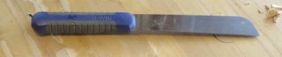
I recently posted about the wonderful little pull saw I bought at Lowes and how I use it constantly while working on the new cedar shingle siding. My only complaint about it is that it is just a smidge too big to fit neatly into any pocket of my old Skillers carpenter vest, a shortcoming I decided to address with other tools. So, I now have three more saws that do fit into one of the pockets, saws that are getting used with ongoing frequency.

The first of these is the little folding Japanese saw that I have had for ages. When fitting individual cedar shingles as one must, I find that there are many times when for several shingles in a row each and every shingle has to be custom cut and fitted, requiring lots of sawing. This is going to occur either on the ground or at the top of the ladder, and given the age and mileage on my knees I prefer it take place up on the ladder. When folded this little beauty fits perfectly in the breast pocket of the vest alongside at utility knife. Perfecto. It is so robust and inexpensive I will probably order another bunch of them so that I can keep one wherever I might need it.
Two other saws were shop made for beefier tasks like localized small scale demo work, which also needed to occur with some regularity as I was cutting away the old cedar siding paneling. Either of them allows me to work efficiently but under fairly delicate control as I was cutting away old materials from around electrical or coolant lines, places where I did not want to fire up the reciprocating saw.
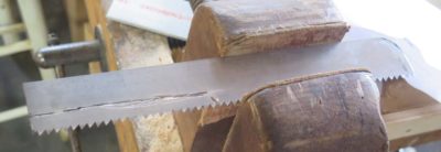
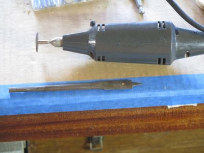
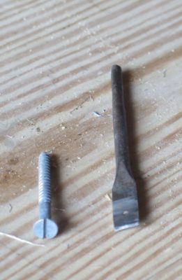
The first of these two saws use a leftover piece of bowsaw blade about 10 inches long. I rounded one end on the grinder and cut the other end of the blade with my rotary tool to remove the teeth and make a shaft for embedding into a handle.

I scuffed the surfaces of the blade handle then sandwiched it between two scraps of wood, using Gelfex epoxy to glue it all together.
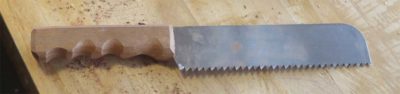
I trimmed and filed the handle to fit my hand and it was off to the races, working perfectly for its intended function.
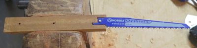
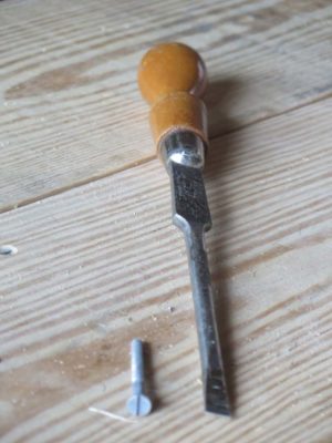
The second shop-made saw employed a blade from the reciprocal saw, the butt of which was inset into another two-piece scrap handle and embedded with epoxy as the handle halves were screwed together.
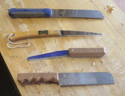
I now have an elegant sufficiency of little saws with large performance.
At many points in the distant past I picked up several pretty far gone saws with the expectation that some day I might get them rehabbed and put back to work. Well, for some of them that day has come and gone and several are now in service. Today I will start with the simplest one.
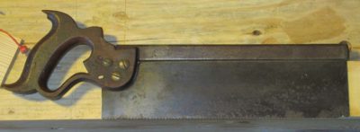
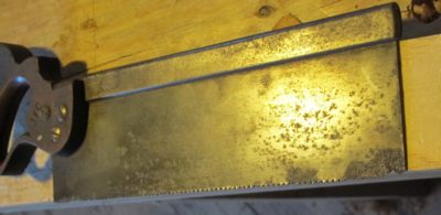
The first saw was a nicely proportioned back saw plagued with deep corrosion pitting on the plate extending up more than a half inch from the teeth at the toe. There was no way I could remove all the pitting from the plate, but I decided to cut the plate back to good metal for filing in some new teeth and at least salvaging the tool. My strategy was to achieve a tapered configuration, losing a good bit at the toe and almost nothing at the heel.
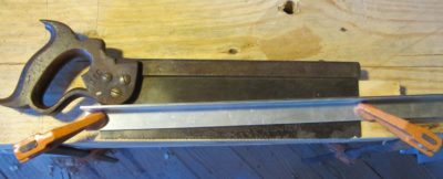
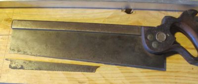
With a carbide scribe, hacksaw, and my trusty rotary tool and a one inch grinding disk (well, several actually) I made the cut, then cleaned it up by sanding the upright saw on my granite block I normally use for restoring edge blades, equipped with a 60 grit belt.
After that it was a very simple matter of re-toothing the saw, I vaguely recall making it into a 16-point ripsaw. Somehow I managed to forget where the pictures of the finished saw are, but you can use your imagination. After getting it to the point I was satisfied I included it in a shipment to Rob Hanson, my personal “Care” packages to a fellow craftsman who lost his home, shop, and business in the California wildfires almost two years ago. I hope he is giving it a good workout.
Which reminds me, I need to get another box of tools packaged and sent to him.
This post is not exactly a “Workbench Wednesday” episode, but since it was an issue and solution that cropped up while building Tim’s Mondo Partner Nicholson Workbench I thought I would put it here.

Normally when I am building a Nicholson bench I slam it together with decking or sheetrock screws and a portable drill. I can usually get one built on a day that way. But with Tim’s bench, because of the setting for the final location of the bench, a restored 18th century log barn outfitted to be an 18th century workshop appropriate to the long-rifle making that Tim does, he wanted the presentation of the bench to reflect the 1780 Virginia frontier. Hence, no decking screws.
Instead I fell back on my old reliable supplier, Blacksmith Bolt and Rivet, who still provides excellent steel screws of the slotted-head woodscrew variety. The quality of these screws versus the usually crappy modern plated screws from the hardware stores makes them worth the effort to obtain and use. For starters, I generally find that about 1 in 25 of the modern hardware store screws actually rings off when I lean on them too much, and the metal is so soft that the heads get boogered up even more often during installation.
Using high quality slotted screws is not without drawbacks either. For starters the screwdriver tip has to fit the slot precisely in both width and length in order to get full efficiency in the driving. Plus, driving large screws by hand is a lot of work and in the case of Tim’s bench I was driving in over a hundred 2″ #14 screws.
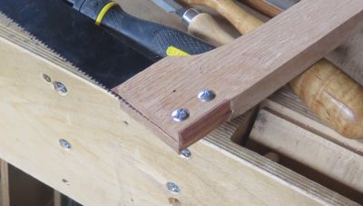
The screwdriver tips I had to fit into my brace were not a perfect fit to the slots of the screws I was using so I took fifteen minutes to make a new one that fit the #14 heads precisely.
I started with the oldest, raggediest 1/2″ wood bit in my collection, 1/2″ being the width of the #14 head. With my handy dandy Dremel-type tool (Craftsman, circa 1975 and still going strong) I took off the central tip of the bit.
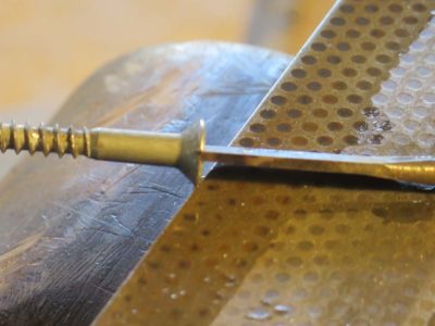
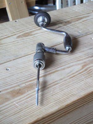
Using a grinding wheel followed by a coarse diamond plate I made the tip perfectly flat and the thickness of the bit to fit the slot exactly, so precise that it literally could be inserted into the slot by hand but still was snug enough to stay there.

With this new precision wood screw bit I was able to drive the dozens of screws easily into the pre-drilled holes. All made possible by the fact that I did not throw away a decrepit drill bit.
Once I finished the marking/mortise gauge for the Japanese tool box I noticed (of course) that the tool box contents did not include a panel gauge. Instantly my gaze swept over to the small cabinet hanging on one of the timber posts, holding several similar tools.
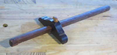
Included there was one set I created from one of my favorite tools, a panel gauge with a Cuban mahogany beam, a rosewood block, and a boxwood screw.


Still, I actually do not use a panel gauge all that much, even one as lovely as this one. But, I like this tool so much that I actually made an additional component for it just for the pleasure of using it more often than otherwise: I made a short cherry beam with a mortise for the cutter to make it a marking gauge as well.
I knew immediately that the scheme would work perfectly for the Japanese tool box with the spectacular advantage that it would consume almost no additional volume. Given the configuration of the irons and the block I could easily make a panel-length beam and simply slide it into place instead of the irons and the clamping pad.
The complexity of the new component was extreme. I had to go to one of my scrap wood buckets and pick out a nice straight piece of white oak left over from making the Studley workbench top, and rip off a square slightly larger than the 1/2″ x 1/2″ hole in the block.
I planed it clean so that it fit snugly through the block and added a finishing nail marking tip which I filed into a sharp edge, and the tool modification was complete.
It fits the definition of a “two-fer” almost perfectly.

There are a variety of mechanisms for clamping a marking gauge’s iron(s) or beam into place but it generally comes down to one of two — a screw or a wedge. I toyed with both options and chose a screw as the simpler and quicker route. The only shortcoming of the system was that I did not have a “nice” screw to use when making it, an embarrassing inventory problem that can be resolved in the future.
In addition to the screw clamp I decided to add a pressure pad to the inside of the gauge block. I’ve always found this to be an elegant add-on as it looks nicer to my eye at least, and prevents the screw from disfiguring the iron/beam.
My first step was to drill and tap the access hole in concert with the screw I had on-hand. (As an aside, I once spoke to a woodworking group about tool making and asked how many had a tap-and-die set. Most hands in the room went up. When I asked how they used the set in their shops, there was a unanimous response of, “Never.” I use mine so much I hardly ever put it away.)
As I alluded all I had was a steel thumb screw, not even a brass one was to be found in the inventory, much less an ivory one. I’ll have to get or make a new one at some point to overcome my shame.


With the screw-hole drilled and tapped I went grazing in the scrap box and found a tiny piece of unidentified tropical hardwood (bocote?) from whence to fashion the pressure pad. This was a mostly filing exercise.
I honed the cutting bevels one last time with a fine diamond stone then cut the irons to length at about 6″, and before you knew it, the tool was finished.


Recent Comments