
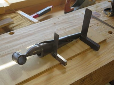
It was a most satisfying day as the upright vise was finished and put into action. I first tapped the threads for the vise screw, and notched the handle for the screw itself. And, the concept of the entire device being easily and rapidly installed and removed with a single whack of a mallet showed itself to be true repeatedly as the day progressed.


With the fundamentals set I made a parallel guide from some 12mm baltic birch plywood from the scrap box, tarted up a bit just because. Two sets of holes were drilled offset as is typical for such a component, and the pin was another piece from the scrap drawer.


I gave it a little test drive and love its performance; whether or not I like it as much in constant and ongoing use will be discovered once I get the other accouterments of the bench completed and put into regular rotation in the shop. One “concern” I have is that I made the off-set of the entire device toward the center of the bench rather than the outside, which would have allowed greater utility for clamping workpieces alongside the outer edge of the slab. Again, only time will tell if I should have done it the other way, and if so, whether Romastonian Bench Vise 2.0 is in the offing.
One of the ultimate beauties of the device is that it takes only a single whack to install or de-install it, and is solid as a rock when in place.
After much consideration of building a Benchcrafted Carver’s Vise to affix to my Romastionian Low Bench, in the end I decided to go a different direction. The BC vise was just too complex and robust (read: complicated/time consuming and heavy) and went simpler and lighter.
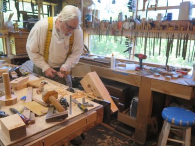
Yesterday was my first day back in the shop, where I went after packaging and sending a bunch of polissoir and wax orders. Mrs. Barn gave me a warning in the sternest possible terms about not injuring myself and treating my knee with care, probably a well-founded warning. Besides, she has more than forty years invested in us/me and she wants to protect her investment. I was cane-free and pain-free by Saturday afternoon, walking more than a mile at a leisurely pace, so I was sure that a low intensity day in the shop was appropriate. So late yesterday morning, able to see my breath in the chilly morning, I headed up the hill to continue work on the Low Bench vise.
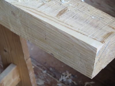
The tapered open socket on the side of the bench was a perfect place to fit a small-ish vise for use while sitting on the end of the bench.
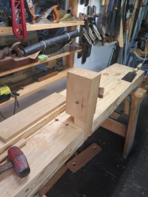
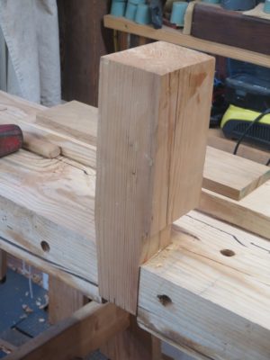
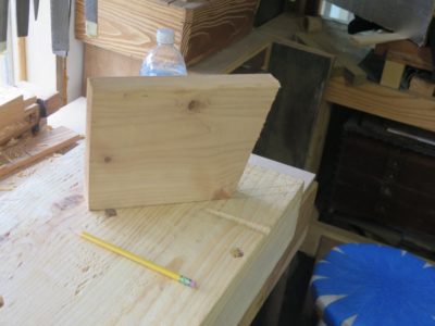
Beginning with a chunk of pine 4×6 from the scrap pile I cut and planed a tapered edge to fit perfectly into the side notch. To make this undertaking quicker I cut a shoulder on the inside of the blank so that the vise en toto would project to the inside of the notch. I decided this was a mistake ex poste, but there you have it. I spent the time necessary to get the nesting just right so that the vise block was set firmly in place with one whack on top, and released easily with a whack on the bottom.


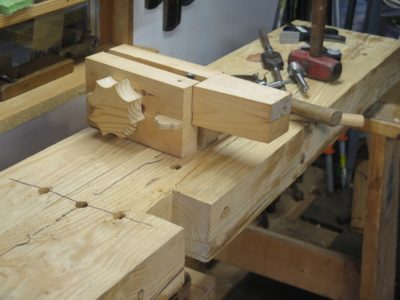
Once I had the housing and tapered block fit just right I marked out the jaw to be cut from the solid block. To make the end result the most precise I chopped the mortise for the parallel guide through the whole mass, then drilled the holes for the screw holes. I drilled a larger hole through the moving jaw face, then the smaller hole for threading by clamping the block in place for the larger hole halfway through, then swapping out the larger bit with one 1/8″ smaller.
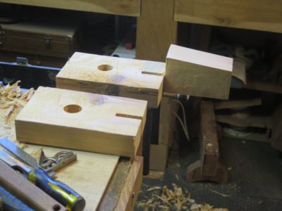
Sawing out the movable jaw was just a matter of careful sawing. Now everything was ready for final work and assembly.
Between travels and other disruptions I have not had much time in the shop lately, a trend that will continue for another fortnight as I get my knee worked on next week.

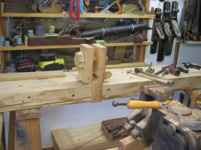
This post is about a discovery of happenstance. I would like to claim this as a brilliant strategic plan from the inception of this bench but the fact is I only noticed it ex post facto. The discovery?

Well, it turns out that the upright carving vise I acquired a decade ago on Craigslist and which has been residing most recently on my gunsmithing bench is almost exactly the correct size to fit into my side notch! Now all I have to do is fabricate a custom wedge to hold it in place and I can use it with impunity. (I also have the Benchcrafted kit parts underneath another bench, so making a similar vise dedicated to the Romastonian Low Bench in is the future.)

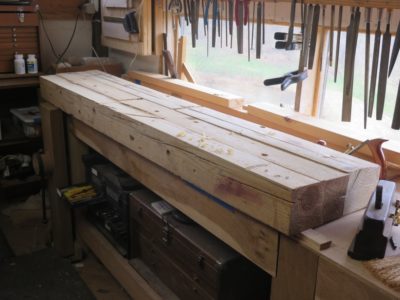
One of the intriguing features of the low benches out and about in the woodworking blogosphere and LAP books is a notch cut into the side edge of the bench to allow workpieces to be wedged into it for cutting on the ends. I decided to give this concept a try on my bench, if it was not to my liking I would just fill the notch back in and move on to other ideas.
The first step was to figure out where to cut the notch, which depended on my own body and working habits. So, I sat down and held out my hands to mimic a long sawing posture, then located the notch a little closer to me than that.
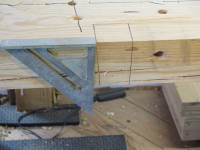
I then laid out the notch to have a square rear shoulder and a tapered front shoulder into which would fit a wedge of that bevel. The exact measurement of the taper is unimportant, it just needs to be slight. I did not even measure mine, I just struck it where it seemed right to my eye.
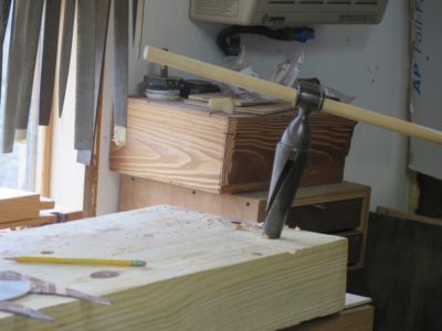
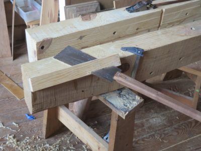
As is my preference for a lot of large-ish joinery sawing I grabbed a trusty Japanese saw and set to work.

My typical procedure is to cut the shoulders of the joint first, then make several cuts in the waste to aid removal.
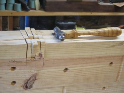


Then I whack the waste with a hammer to remove as much as I can, leaving the remainder for the hammer and chisel, followed by a rasp.

With the notch cut I fashioned a wedge to fit the taper and gave it a test drive. I will no doubt make a number of similar wedges of differing thickness (or perhaps a series of spacing shims) to accommodate a great variety of workpiece thicknesses.

I worked it a few minutes and liked the concept very much.
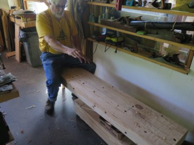
With the slab established and the staked legs in place and trimmed to length the time had come to start tricking out the bench. Needless to say I blended existing ideas with some new flavoring of my own. In this episode the emphasis is on 3/4″ holes. Lots of them. My slab was over 4-inches thick so I was not too worried about weakening it. If it were a 2-inch slab I would have been more cautious, but a 4-1/2-inch slab is inherently stronger than 2-inch by a factor of almost eight (cross sectional strength being the ratio of the two cross-sections to the third power).

The starting point was the reality that I was using a recycled planing beam for the bench slab so some holdfast holes were already in place, sort of. This was particularly relevant on the edges of the slab. All I had to do was deepen the existing holes in order to make them amenable to holdfast use. Edge holdfasts are not usually incorporated into low benches, but here the opportunity was too rich to pass up.
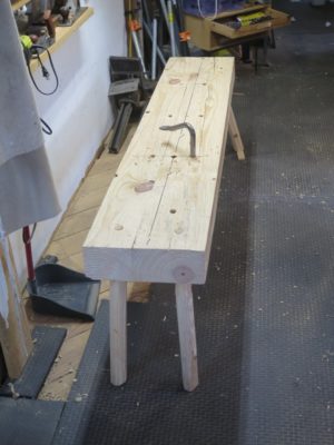
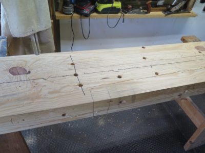
In addition to the edge holes, a low bench requires a number of vertical holes through the slab in order to use both holdfasts and aligning/wedging rods to facilitate upright edge planing. With a spacing strategy that will become more apparent in a couple weeks, I drilled and added these devices.
I am not entirely pleased with the splay of the staked legs on the end closest to the camera so I may re-drill them. This is the end I will be sitting on most of the time when using the bench. I am perplexed as the angles of the far end legs are perfect. I must’ve not had the template in the right orientation (closer examination suggests this as the most likely culprit) or was distracted by some compelling point in a podcast or a captivating riff on a CD or whatever.
Stay tuned.
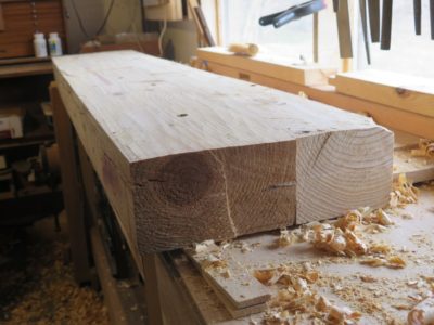
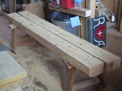
Given the “new growth” nature of the wood it took only short time to get the bench slab flat enough to move on to the staked legs.

For the leg material I was able to recycle the hunk from the edge of the original slab when I ripped that to the width I wanted. I made five leg blanks just in case.

To guide my tapering of the ends I made a quick template based on my tapered spiral reamer, bought for a song at a tool flea market.
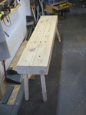
I laid out the holes for the legs by insetting them four inches from the side and end, then angled out at 12-degrees on the diagonal. I drilled 3/4″ holes all the way through from the underside, then reamed them with the spiral taper until the taper intersected with the top. In retrospect I should have made the angle a bit more, perhaps 16 or even 20 degrees, but I think this will suffice. If it does not, I will simply move the hole location and drill new holes.

Once I had the leg ends tapered with a drawknife and block plane I just drove them home into the reamed holes with a small sledge. They seated with a crisp thunk. I tried several heights for the bench with a series of mock-ups, and once I determined which height worked best for me I measured the legs and cut them off.

Rolling the bench over and putting it in place this step was finished. Now it was time to begin tricking out the bench.
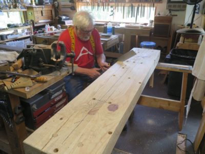
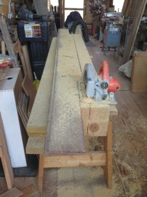
With the two timbers glued into one slab I pulled out my trusty scrub plane and started hogging off material since the wind was a tad pronounced. I was able to get the initial pass finished out in the great room of the barn, and again put my mighty 10-inch circular saw to work cutting the slab to the 13″ width I wanted. As with the initial timber splitting I was left with an inch or so to cut by hand.
Moving the sized slab onto my Roubo bench in the studio I employed the Roubo technique for achieving the flat plane of the slab.


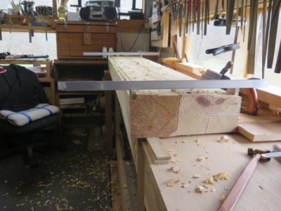
First I shot a rabet down each edge of the slab, using two pillared winding stick to determine when they were perfectly parallel to each other. My original Roubo winding-sticks-on-stilts were unavailable so I just used two hardware store aluminum bars sitting on identical blocks. Once I had the parallel edge tracks established I grabbed the scrub plane and got the surface flat in about a half hour each side. It’s worth noting that even though the wood was southern yellow pine, it was new growth SYP and much less dense than the timbers from the barn itself.

Next, it’s on to the staked legs.
My first exposure to the existence of something called “a patternmaker’s vise” was in 1978 when I went to work in an actual pattern shop. Although I had been engaged in woodworking at increasingly sophisticated shops for several years by that point, the Emmert vise was unknown to me. My job at the pattern shop was a 7AM-3.30PM shift, which was a struggle for me since I am a night owl by nature and getting up to work on time was a challenge even though it was only a three minute bicycle ride to the foundry from my house. But, that work schedule allowed me to have plenty of afternoon and evening time in the shop I built behind the house.
I was so entranced by the Emmert that I checked into buying a new one from Kindt-Collins, the Cleveland based foundry supplier who was by that time the manufacturer of the original Emmert K1 vise. I cannot recall exactly whether the new one was priced at $1750, $2250, or $2750. All I knew was that there was no way I could afford any of those price points in 1978. I did obtain a pair of Emmerts right after Mrs. Barn and I married and went to Delaware for college in the beginning of 1982. The Philadelphia Navy Yard had recently closed their foundry so there was a huge stash of Emmerts just up the road at a Philly machinery salvage outfit, and I think I paid $200 for my pair.
At least one of mine has always been installed and the center of my workspace ever since. I cannot really imagine a workshop of mine not having one.
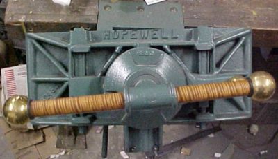
Last week my pal JohnR let me know that the Emmert vise may have been rebranded as “the Hopewell vise” and back in production. The information is at the following link. Maybe this is already known throughout the woodworking blogosphere and I have just been too wrapped up in my own activities, but here it is.
CS Machinery (mprime.com)
If you have always wanted a brand new, incomparable patternmaker’s vise this could be your chance. I have no connection to the new maker and have not encountered one of these vises, but I would love to know more myself.
As I once told an aficionado of workbenches, “If you have avoided using an Emmert before, do not start now because you will be black and blue from kicking yourself for not trying it earlier.”

With my former planing beam cut almost all the way through using my trusty 10-inch circular saw I was left with sawing the last inch of thickness by hand. Grabbing my equally trusty ancient 3-1/2 t.p.i. handsaw I made short work of the separation, getting almost 1-1/2 inches of cut per stroke.

I then made a nuisance mistake by cutting off the wrong end of the timbers I was only going to make a six-foot bench). I should have cut of the end with the wainey edges, but instead I cut off the nice crisp end. So now I had to take a few minutes to plane flat the rounded edge and glue on a new piece in order to make it square.

That I accomplished by just sawing off and hand planing the excess.

With the pieces separated I dove in with my scrub plane to get everything more or less planar by eye. The beam had a bit of wind in it which became exaggerated (doubled) by the splitting. Once the mating surfaces were flat-ish, or at least fitted each other nicely, I got out my fave toothing plane and got it mated for real, ready for the, er, mating. In this instance I used PVA, in part because I did not know the final environment for the bench but really because I had not prepared hot hide glue in advance and thus had none ready to go when I was determined to execute the glue-up.


It is really comforting and confirming when the squeeze-out is uniform through the length and breadth of the joint.
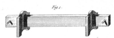
My friend Justin sent me another picture, this time from the 1882 Boston Directory. Very exciting!
Is this where Studley got his bench vises?
The hunt is afoot.


Recent Comments