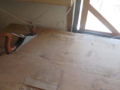
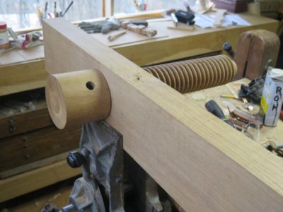
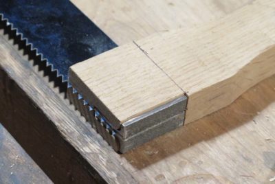
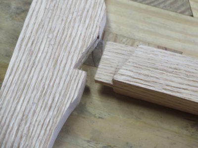
One of my quirks is that I usually like to lay a piece of sacrificial sheeting on top of my workbench most of the time, and today was my day to swap out the old one for a new one on the FORP Roubo bench. As I was making the swap I noted that it was also time to address one of the two main manifestations of Seasonal Affected Disorder that afflicts (?) wood in the natural course of events, sometimes called hysteresis, sometimes called rheological cycling, but generally known to us folks at the workbench as “wood expands, wood contracts.” One of the consequences is that when there are pieces of wood assembled with different grain orientations eventually they get out of sync dimensionally. In a Roubo workbench this become manifest as the tops of the leg tenons eventually protruding past the top of the slab.
As I was fitting new pieces of luan plywood to lay on the bench top I noticed that the tenons were quite proud of the slab, perhaps 1/16″. I only assembled the bench a couple years go and did not notice the issue when I laid the initial sacrificial covering at the time, but it was there now.
You might have thought that since the bench was initially fabricated eight years ago it should be fully settled into its new environment. Maybe, maybe not. If the old adage that wood seasons at the rate of “one year for every inch of thickness” is true then the answer would be “yes.” Since I moved to the hinterlands and talked to some of the local wood guys I have come to appreciate their view of seasoning woods, especially dense hardwoods. To them “one year per inch” does not hold true; instead they use a formula of “one year for the first inch, two additional years for the second inch, three additional years for the third inch,” and so on. By that metric my five-inch-thick bench top will pretty active for 1 year + 2 years + 3 years +4 years + 5 years, for a total of 15 years.
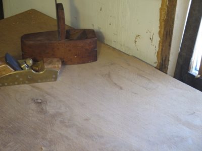
I dealt with the tenon ends directly in about an hour this morning, and will address the slight crown of the overall bench perhaps at the end of summer.
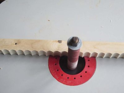
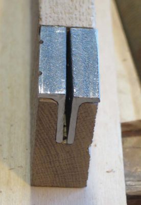
It might be worth reiterating that once I get a slab bench top flat I prefer to hit it with a toothing plane to give it a little texture. I lose none of the planarity but gain a lot of grip on the workpiece.
While browsing around the interwebz over the weekend I noticed that Rex Krueger featured Roubo’s winding-winding-sticks-on-stilts from our Roubo on Furniture volume. He is to be commended for bringing the message of hand-tool woodworking to a new audience.
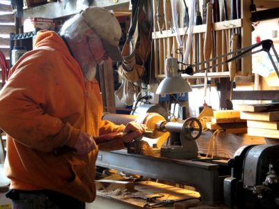
As our recent week of Ripplemania III proceeded we were both making progress, albeit not entirely unhampered by glitches along the way. John was very much involved in locking in his wave function (side-to-side) while I was dialing in my new swing-arm cutting head for narrow-ish ripple moldings.
Once I got the free weight on the pivoting head right it started producing some very nice moldings. The anvil weighed just the right amount and I could slide it back and forth to adjust the force on the cutting tool, heavy for the initial cuts then lighter for the finishing cuts.
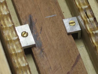
I also wanted to standardize the workpiece-holding aspect of the platen and spent some time making new clamps from a piece of aluminum angle stock, This approach worked extremely well.
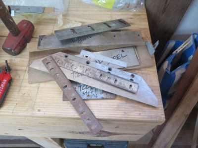
Another thing we did during the week was gather all the tool steel I had in my inventory to begin the work on making new cutters. I had already ordered a variety of tool steel bars over the years for one project or another, when combined with the “used” tool steel I also had resulted in quite a pile. Since I never throw away old planer blades there were a number of them, but the real treasure was the stack of hefty blades (~1/2″ thick) from a book producer’s guillotine that my pal Tom passed along to me. These massive chinks will yield a large number of cutters, probably more than I will ever need. I spent several hours working on a new cutter pattern for my machine but did not get that blade finished during the week.
Even before this week of prototyping John’s machine had ripple molding cutting nailed. So, he pretty much spent the week trying to do the same for the wave molding cutting function.
In working through the problems of wave molding cutting John kept running into the hurdles caused by the elegantly complex head he had created for his machine, one that could do either wave or ripple moldings, and ideally even both simultaneously. This was a really complex problem that expressed itself in a number of hiccups due to the lateral forces being exerted at the cutting edge. He definitely made progress but the problem of the lateral forces and their effect on the cutter-head were not fully solved.
My issues were much simpler, just get a cutter head and workpiece holding system suitable for scratching out a simple pattern. One of the things I decided almost immediately was that my machine was too low to the ground, especially when cranking the handle to drive the moving platen, so I just hoisted it onto a pair of low sawhorse. That helped my attitude immensely.
Last month my friend Ripplin’ John and I spent a week in the barn working on and brainstorming about our respective ripple molding machines, trying to get a model ready for the show-n-tell of Handworks 2020 (this is before we knew Handworks 2020 was being postponed by the Wuhan Virus). I had made a little progress on my machine since Ripplemania II but he had made great strides with his. During the week his main emphasis was on the lateral “wave” cutting function of his elegant machine while I was simply trying to get my newly designed cutting head to work properly.
Prior to our most recent week together I had also been working on the notion of improving the method and form of the ripple patterns themselves. I tried a number of different methods and jigs but wound up realizing that precision layout and careful workmanship was the key to producing a crisp, precise concave pattern. Throughout our week we discussed this issue and I am now thinking that concave is not the way to move forward, convex patterns may be the future.
As John was assembling his machine, a fairly lengthy process since it was totally disassembled to fit into hi vehicle, I was puttering on mine.
My new cutterhead was now configured with the cutter being positioned at the end of a long weighted swing arm rather than inside a spring-loaded modulating frame structure.
I reasoned that the swing arm was a simpler approach and determined to give it a try. Unlike John I narrowed the scope of my machine to do only one thing, namely cut ripple moldings of approximate 1-1/2″ stock width and 1/2″ thickness. No wider, no thicker. Thus my machine structure was much more restricted than his with approximately zero adaptability.
John had been working on two important evolutionary steps. First, the machine could cut but ripple moldings and wave moldings within the same overall machine structure. Second, that the machine could be mechanized and automated thus making it a more practical device for producing large quantities of moldings. As he recited a truth to me, “Turning the platen drive handle gets old after a surprisingly short time!”
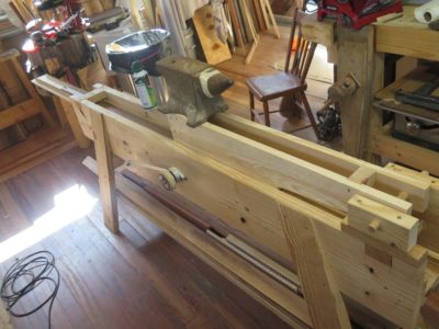
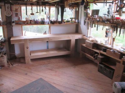
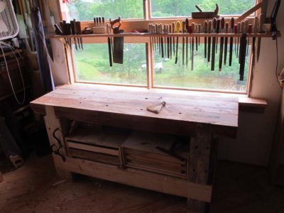
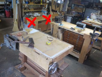
… for my FORP Roubo bench to find its rightful home underneath the bank of northeast-facing windows.
As I’ve mentioned previously the spatial arrangement in my studio has been undergoing reorganization, or as James “Stumpy Nubs” Hamilton calls it, “rearrangeritis.” In one sense I am living with the curse of too much space, thus I need not be particularly efficient with my shop layout nor unduly burdened by the necessity of tidiness. I am trying to improve on both counts.
After completing the construction and assembly of my 2013 FORP workbench last year I planted it on the north wall of the shop, thinking that would be a good place.
I was wrong. I back-filled the space around it with my favorite little two-sided workbench and some other stuff and before long the whole space was a chaotic mess.
Plus, that new space was so crowded it precluded me even installing the superb wooden screw leg vise that was part of the original design. In the original configuration the four inch round block plus the three inch moveable jaw would have made the whole thing stick out too far to even walk past easily. There simply was no room to use it even if it were installed so it remained on the sideline.
After much cogitation I decided to move it underneath the large bank of windows facing east. This was not done lightly — rasslin’ an 8-1/2-foot, almost 500 pound workbench by myself is not something to undertake on a whim. I set aside a day to move the bench and the other nine things that had to be moved first in order to accommodate the move around the corner, but it was absolutely worth it.
This should not have been a huge surprise to me as it was the location for my first Roubo workbench built from timbers left over from the barn re-erection. Truly, this was THE right location for the bench and I was an idiot for not recognizing this from the git-go.
I now have a sublime arrangement of my beloved first workbench sitting in the middle of the floor at that end of the shop with the Roubo a simple body-rotation away. The arrangement continues to make every day in the shop an unfettered joy.
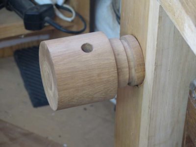
In addition to the move itself I finally finished the installation of the Roubo’s leg vise after first reducing the thickness of the jaw from three to two inches and reducing the size of the bulbous block that was exactly at knee height and stuck way out into the work space.
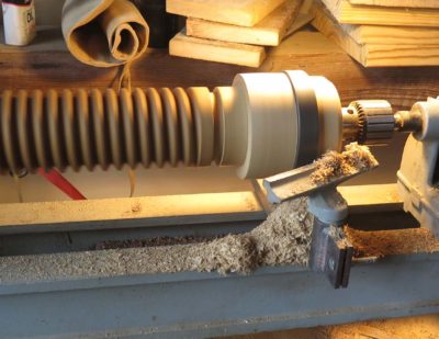
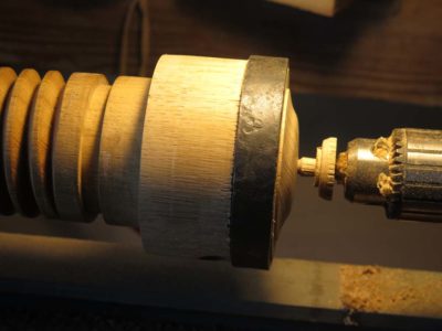
To reduce the number of times I whacked it with said knee I tossed the vise screw in the lathe and cut down the outer terminus block by an inch in length, moving the wrought iron collar right up against the handle holes and shaping the end, yielding a result much more to my liking than the knee-cruncher originally made. In fact completing this feature was one of the motivating reasons behind the move.
Using an outrigger stand temporarily until I get the sliding deadman built the bench works just like it is supposed to.
The integration of the massive Roubo into the workspace has other meaningful implications as well, almost like the ripples radiating from a stone being tossed into the pond. Not the least of these effects is the rendering of the planing beam as redundant, clearing up that particular space in the not-too-distant future. I may use part of that space as home to the full-service standing tool cabinet I have always wanted. If so I will have to find a new home for the exquisite vintage mahogany I have stored underneath the beam. Some of the other re-arrangeritis is more subtle as I will build a small, low Roubo bench for the space where the giant Roubo bench used to be. This lower bench will allow me to work for long stretches while sitting. As I get older I find the Eastern tradition of working while sitting down is all the more attractive; I actually do not mind working while standing, it’s the bending up-and-down that wears me out.
All things considered I am thinking that these changes will result in higher shop production-ableness while reducing the total footprint of the space.
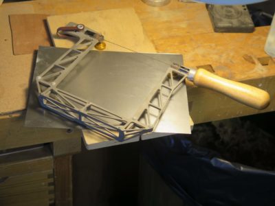
The conceptual foundation of this saw is the ability to rotate the saw blade within the saw frame. When noodling the design and fabricating this hardware element I considered many options before settling on something nearly identical to Roubo’s.
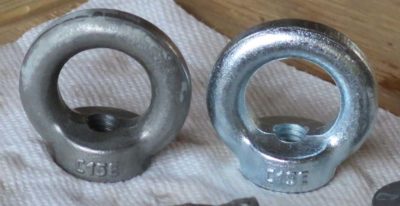
I ordered a variety of of sizes and configurations of eyebolts from McMaster-Carr to play with.
The eye large enough to accommodate or incorporate the 1/2″ cylindrical rod for affixing the blade was simply too huge for the proportion to work properly. The eye of the correct proportion was made for a threaded rod way too small for the 1/2″ wide blade. In the end I took that smaller eye and drilled and tapped it for the cylinder rod of the right size.
I split the eye bolt with my jeweler’s saw and a #10 blade. I then drilled the cross-holes through which the blade could be attached to this split rod.
One of the last things I did before assembling the whole saw was to de-zinc the hardware parts by soaking them in a citric acid solution (about 2 tsp/pint of water). As soon as the mild acid began to work on the zinc the solution got cloudy. I had to monitor the progress and removed the hardware when I had gone far enough.
I assembled everything to make sure it fit but I did not give the saw a test drive since I did not have the saw blade that would be used for it.
I disassembled it and shipped it off to Wisconsin. I cannot wait to get a production prototype back to give it workout.
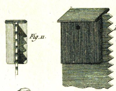
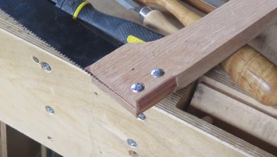
With the Roubo Joinery Saw prototype winging its way to Wisconsin I turned my attention to, well, Roubo’s “turning” saw from Plate 12, Figure 5. I used the identical design for the overall bow for the Joinery Saw, but there were more than enough twists and turns along the road to make it interesting.
The term “turning saw” has two particular meanings. First, the saw plate is narrow enough so that it could be turned as it worked its way through the workpiece. Second, the plate itself could be turned in the bow, enhancing the capabilities of the tool.
I began from the premise used in the Joinery Saw, namely that I would be trying to replicate Roubo as closely as possible based on his illustrations and verbal descriptions. As before I used white oak for the wooden elements. For the saw plate I just used a broken band saw blade since Bad Axe has not yet begun to develop theirs.
Thus the two crucial differences were the housing at the end of the bow arms through which the round spilt post passed, and the split post itself.
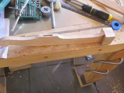
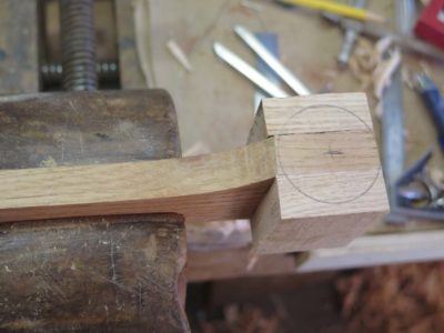
The bulbous end block was the simpler of the two problems to solve. I glued scrap blocks in place, laid out the bulb, and shaped it to the design. Drilling the hole for the post was simple enough.
I think that when creating a production-worthy Plate 12, Figure 3 prototype at the request of Mark Harrell of Bad Axe Tools, I spent the most time and creative energy in working out the problem of retaining the saw plate in the bow saw arms.
My first effort two years ago worked well enough for one guy making one saw, but it was IMHO insufficient for any kind of production run. The amount of work necessary to excavate the base of the wooden arm in order to receive this particular two-piece stirrup configuration made this option a non-starter.
Plus, like the configuration of my original Art Nouveau-ish bow saw frame it bore little resemblance to Roubo’s illustration. His description and illustrations clearly represent a folded “T” shaped fitting-with-pin for holding the saw plate in a slot at the bottom end of the arm. So, that is the direction I headed towards. At this point my only fundamental deviation from Roubo was that Mark’s saw plate had two holes rather than Roubo’s one.
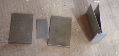
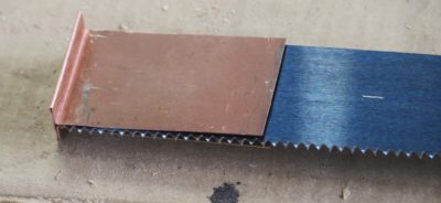
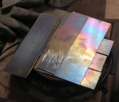
I ordered some 1/32″ steel sheet, unfortunately it did not come in narrow configurations so I wound up sawing it by hand until I had pieces that would fit into my little shear/brake. Once I had the strips in-hand I started the process of figuring out how to accomplish this tricky series of bends. Fortunately I had my sweet little shear/brake from Micro-Mark to help me. Sort of.
I found that the brake’s bending was so crisp that the steel snapped off at that point. Actually, what happened is that I could bend crisp 90-degree corners then had to spread them in order to bend the next set of corners, then bend the original corners back. That’s when they snapped. I eventually did figure out how to get it done (see below).
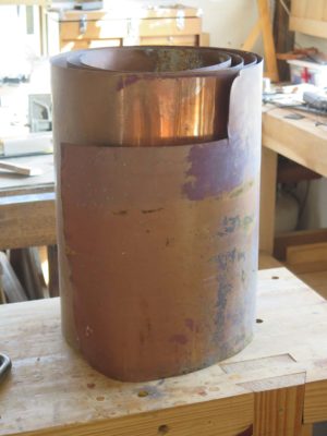
After the steel sheet gave me trouble, before I figured out the solution I tried some .030 copper flashing I had sitting under the stairs in my hardware store. It cut like butter with my engraver’s hook and folded in the brake without a hitch. (I swear I do not know why Photoshop and WordPress cannot play nice with each other!)
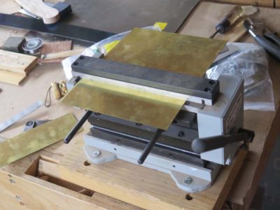
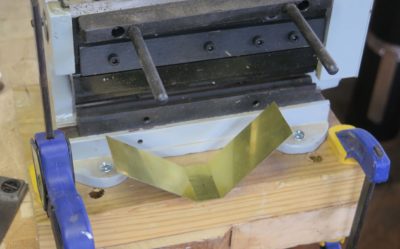
Since copper worked so nicely but was pretty soft I decided to try something halfway in between, .030 brass. Unlike the copper it was really stiff so I annealed it on my hotplate before trying to bend it.
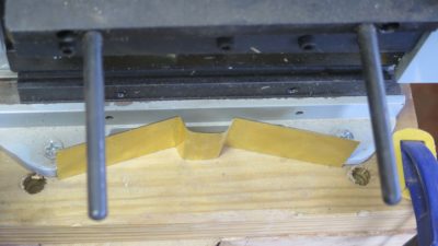
By this time I had hit on the solution to the earlier problem that caused the first steel stirrup to snap. Instead of making the first bends to 90 degrees then bending them open, I bent them only enough to establish the corner.
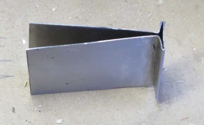
This allowed me to use the brake for the second bend. Then by hand I could fold the unit closed with a hammer and cold chisel until it was in the “T” configuration.
I worked this system in all three materials and found the solution to be darned near perfect.
I drilled out the stirrup and arm to match the holes in the saw plate and held the entire unit together with binding posts. I apologize for not taking a picture of this assembly all by itself.
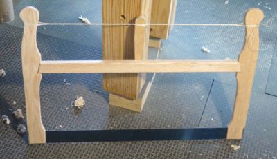
With the entire stirrup now passing through the bottom of the saw arm there was virtually no joinery involved; just make the slot for the stirrup and plate, widen it a bit, and slip it all together. Inserting the binding posts completed the assembly of the saw and all it needed for working was the windlass and cord. I used a much smaller windlass bar than my earlier one, about 1/3 of the weight of that one.
I took pictures, dismantled it and shipped it off to Wisconsin.
Aside from the fact that my first effort in producing a joinery bowsaw based on the Bad Axe saw plate didn’t look like Roubo’s, only one of several features rendering this prototype useless to Mark in designing a production run, it was way too heavy at over six pounds. That extra weight was fine for when the saw was engaged but sure was a nuisance when trying to maneuver it in between cuts.
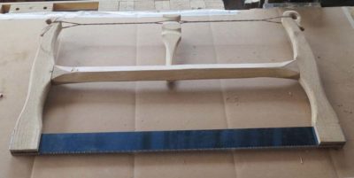
So, I went back to the starting point and recut all of the wooden elements to both be slimmer and look like the saw Roubo illustrated in Plate 12, Figure 3. In the end the only dimension that remained unchanged as the length of the saw plate. Everything else was thinned, widened, thickened, or narrowed as I felt necessary.
The resulting weight reduction of almost 25% was noticeable immediately.
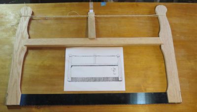
I literally enlarged this image to almost life size when creating the template. Again I used some of my stash of clear white oak left over from the fabrication of the Studley bench top for that exhibit five (!) years ago.
The cutting and configuration was straightforward in the gross sense, but I spent a lot of time getting the template for the end pieces just so, reflecting the illustration Roubo created for the tool. This is a tricky proposition, as the proportions and details of tools are not always perfect (see Plate !! for confirmation) but it had to be closer than the Art Nouveau-ish version I created for the first one. Once I was happy with the shape and proportions of the arms I made a solid template from which I could make as many tracings as I wanted.
Of particular interest to me was the juxtaposition of the stretcher to the end arms; the only way the saw made sense in the flesh was to have the stretcher be notably thicker than the arms. So that is how I made those three pieces. In the end I made the stretcher about 1-1/16″ and the arms 3/4″. I fussed over this detail for a couple weeks.
Notching the arms to receive the stretcher was also an issue as I had to make sure the strength of the arms was not compromised by too large a mortise. I accomplished this by making sure the loose mortise-and-tenon assembly was quite thin, just a bit over a quarter inch and shallow at a half inch. Since the joint’s only purpose was to keep the pieces in alignment that worked out just fine. All the stress was in compression so the tighter the windlass was turned the more solid the bow structure became. Unless, of course, it broke. Hence my fussing.
But that was not the worst of it as noodling and fabricating the stirrups for the end of the saw plate was way more problematic.
Some time ago I was asked by Mark Harrell of Bad Axe to build production-able prototype versions of the bow saws Roubo featured in L’Art du Menuisier, Plate 12, Figures 3&5. He was considering adding them to their product line and I was delighted to collaborate with him as I would be with any tool producer.
My first effort two years ago resulted in some success but some failure, so in recent weeks I have been trying to extract more of the former and expunge the latter. My first attempt yielded a prototype that was unsatisfactory in the important aspects of the tool; 1) it was way too heavy, 2) did not look anything like what Roubo described and illustrated, and 3) had plate fittings wholely unsuited for manufacturing (yes, I know I spell wholely different that the dictionary; the dictionary is wrong). So, I went back to the bench and started all over again.
In the coming days I’ll walk you through my successful attempt at Version 2 of the Joinery Saw..


Recent Comments