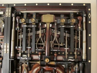
My friend Tom standing in front of Walt’s tool cabinet when we were visiting him in Staunton. I very much like this style of standing tool storage.
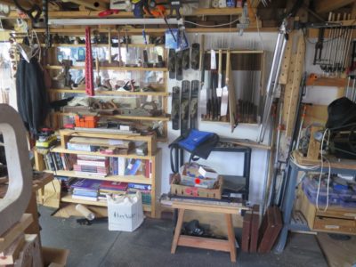
For a variety of reasons – desire to consolidate my core tools into a compact-ish volume in preparation for the “some day” time when I do not have a 7,000 s.f. barn, organizational order (my friends are laughing out loud right about now); work flow; parquetarian/channeling-Studley indulgence; antipathy for floor level tool chests — I plan to spend a good part of the next two (?) years constructing, decorating and outfitting a large standing tool cabinet in my studio. It will reside in the space currently dedicated to my saw rack and whatever is on the floor underneath it. I was really impressed by my acquaintance Walt’s cabinet and plan to use his as an inspiration for mine.
Rather than making it out of solid lumber with dovetailed corners my plan is to construct the box/doors entirely from 3/4″ & 1/2″ Baltic-birch plywood and sheathed in a yet-undetermined parquetry pattern (a la Roentgen?) using veneers sawn from leftover FORP workbench scraps. This project has been gestating long enough that I scrounged scrap 18th century French oak from the original Roubo bench-building workshop in Georgia.
The cabinet box will be roughly 48″ high x 42″ wide x 16″ deep with an open space between the base structure large enough to fit my Japanese tool chest.
Leave it to me to attempt a masterpiece project that almost nobody will ever see.
One of the truly exasperating aspects of the Gragg chair workshop was that my 10″ benchtop bandsaw was continuously malfunctioning, requiring us to go up and down two flights of stairs to the main floor with its two larger bandsaws instead of using the little beauty up on the fourth floor. Chairmaking does not require fancy band sawing but it is an important contributor toward making it an efficient process.
After much sturm-und-drang I discovered ex poste that the new 1/4″ bandsaw blades I’d had in the drawer for the 10″ unit were mismarked; instead of being the 56-1/8″ needed they were 59″. I could get them on the wheels and run true when turning freely but they would not stay there once battle commenced. I ordered new blades and they were the right size, so with a complete cleanup and adjustments, combined with new guide blocks cut from a rod of 1/8″ carbon fiber rod from my stash, the new blade installed and ran perfectly and now once agin the saw cuts superbly.
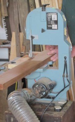
Meanwhile I decided to tune-up my 40+-year-old 14″ Delta bandsaw, a prize from a yard sale almost 20 years ago. I think it was $100 complete with rolling base. For a long time I had been contemplating adding a true rip fence to the saw, and finally made the plunge. Even though the Kreg fence is designed to be installed on the left side of the blade, with a little tweaking I installed it where I wanted it on the right side of the blade. Sweet. I also finally added a dust collection port in the lower wheel cover, which combined with a simple bent sheet metal cowl around the lower guide block unit, reduced the sawdust by roughly 95%.
I am contemplating but have not acted on purchasing a carbide tipped blade for the band saw; the ~$200 price tag is a bit stiff. If you have had any experience with carbide tipped blades for small bandsaws please let me know.
BTW here is an excellent short video on bandsaws that I discovered recently.
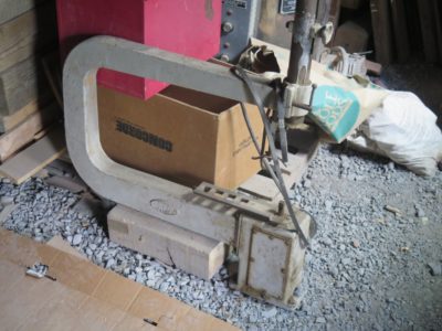
So, I’ve got this ancient 1930s era scroll/jigsaw, a Boice Crane Model 900. It is to my mind the tool form against which all others are measured. Acquiring it was my introduction to Tall Tom, my woodworking pal of lo these many years. He was at a community yard sale selling tools and carved walking sticks and had a small vintage Delta scroll saw at his booth. I checked it out and decided to pick it up on my return trip after browsing the yard.
It was, of course, gone when I did return. I engaged the seller (Tom) in conversation. He mentioned that he had another one back at the shop but it was too heavy to haul to a flea market, so we arranged for me to come see it at his shop. In the end we agreed to a trade; I would give him some turning lessons and he would give me the scroll saw. Little did I know that for many years I would be found in his shop on Wednesday evenings, and that he would make several trips with me to the barn (the picture is from 2011).
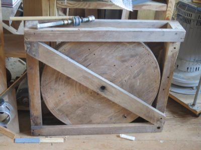
I am determined to get this saw rejuvenated and outfitted for marquetry work. Since I have a large wooden wheel I made for a treadle lathe, why not combine the two and make the Boice Crane something akin to a Barnes Velocipede Saw on steroids? If it works out it would be a superb marquetry saw.
One of the aspects of having a humungous Fortress of Solitude like the barn, four stories of 40′ x 36′ space, is that there are a multitude of nooks and crannies into which things can be tucked, stuffed, crammed, lost, and re-discovered. I call these instances my own “Clean Up Christmases,” when I come across treasures I had forgotten, or at least misremembered.
Such has been the case recently when prepping the classroom for this coming weekend workshop Historical Wood Finishing. As the first class there in over two years, the space had, shall we say, devolved. That pesky Second Law of Thermodynamics; they tried repealing it but it just didn’t take. It has taken me over two weeks to get it ready for the group on Saturday. The level of “rearrangeritis” (full credit to James “Stumpy Nubs” Hamilton for coining the phrase to describe an all-day travail when moving one thing in his crowded shop) has been monumental, and monumentally rewarding on several fronts. It has also given me time for contemplation about future projects, a topic I will address in numerous upcoming posts.
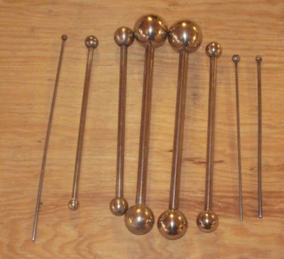
At the moment I am mostly reveling the rediscovery of two caches that were set aside for some future completion. The first is the two sets of brass Roubo-esque squares fabricated before and during that workshop more than two years ago; all it will take is a day or two with some files and Chris Vesper’s sublime reference square to get them up and running.
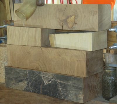
A second trove is the pile of French oak scraps from the multiple iterations of the FORP gatherings in southern Georgia. I brought them home in order to turn them into veneers, probably oyster shell style, to use on some as-yet-unknown project. That “unknown” identifier is becoming more “known” as the days go by. Then, much like my shop being the only one in the county with two c. 1680 parquetry flooring panels from the Palais Royale in Paris, my tool cabinet will be the only one with veneers from some c.1775 oak trees from the forests surrounding Versailles.
Who knows what other “Christmas” presents I might find during the never ending effort to impose order on my space? Stay tuned.
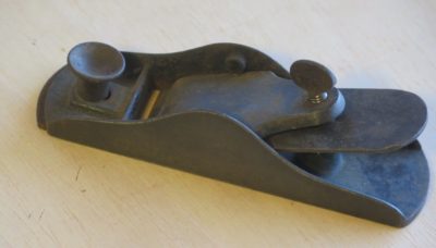
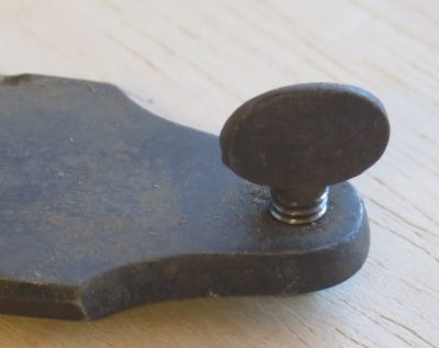
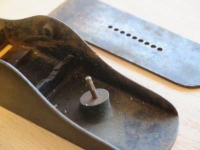
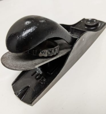
During a recent dive into my inventory of block planes needing restoration the lines of this one caught my eye. It was comely, with a very low angle so I immediately thought it would be a good candidate for me to restore for my son-in-law. Sure it was void of any adjusting controls but he knows how to adjust a plane manually with an iron-setting hammer.
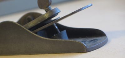
At second glance there was something hinky going on with the plane. Was the iron sitting in the pin?
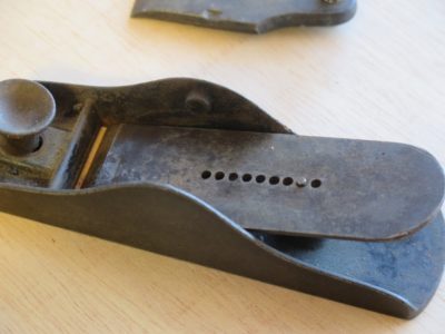
Once I took it apart the confusion set in. What the heck? The way I read this tool, with the iron not resting over the pin but impaled on the pin, the iron is utterly and completely un-adjustable! In one sense the tool is on the “primitive side” given the ostensible lack of mechanized adjustments. Bur completely un-adjustable? Given the general quality of the plane design and quality execution, I’m just left scratching my head.
At this point I’m noodling soldering on a block over the pin and using the tool as I first figured it was designed. Or is the pin malleable and designed to be whacked back and forth with the iron?
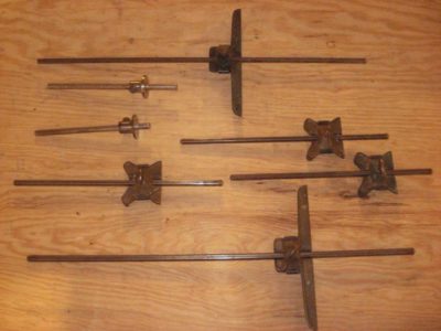
At first glance the patternmaker’s tool kit might seem nearly identical to that of the furniture maker. Scribes, squares, dog-leg paring chisels, marking gauges (of which this kit had more than a half-dozen) etc., are identical even though their uses may be a bit different. But the tools are the same.
Even their differences might be chalked up to meaningless peculiarities, but they are not. Here is a brief review of some if those items unique to patternmaking, or uses of typical tools for particular applications.
Shrink Rules/Scales
Especially at the industrial scale resides the inescapable fact that molten metals shrink when they cool and solidify, and the degree of shrinkage depends on the metal alloy in question. For this reason the patternmaker’s kit includes a variety of precision rules that take shrinkage into consideration, and when a new pattern is commissioned the drawings are transferred to a full-scale master made on a new piece of hardwood plywood with the dimensions established by the shrink scale. In other words if the item being designed is to be 12″ long, in true measurement it would be 12 inches plus some fraction, but all of the scale delineations are created proportionally. Thus when we were making pump shell patterns for dredging operations, our main business, sometimes those patterns would measure 6, 8, or 10-feet in diameter (or even bigger). When cast in grey iron the patterns for a 10-foot shell diameter were actually 10′ + 10/8ths inches in diameter (10′- 1-1/4″) since the shrink rate for iron is 1/8″ per foot of dimension. This issue is rarely a fundamental consideration for the scale at which I cast these days. For example when calculating the shrinkage on the Studley mallet bronze shell, with an overall dimension in the neighborhood of two inches given the shrink rate of bronze as 3/16″ per foot, the mallet shell casting would shrink 1/6th of 3/16″ or about 1/32″. Even though I will use a shrink rule to lay out the pattern, I could probably get by without it. Once I get done casting the mallet heads I will be moving on to patterns for the Studley piano maker’s vise, and that will be large enough to use the shrink rule for sure.
Dividers and Trammel Points
Dividers are critical for transferring the shrink-layout dimensions to the pattern itself. This speaks to the importance of the master layout, usually executed on a pristine piece of hardwood plywood, as patternmakers realize and generally live by the ethos that “measuring is the enemy.” If you get the master layout correct it is a regular routine to use dividers and trammel points to transfer and establish all dimensions for constructing the pattern from the layout. In fact once the master layout is completed the only thing I can recall using the shrink rule for was when planing the laminar sections for stack laminated construction that was the norm when I worked in the trade. I think it is pretty much a dead trade, nowadays everything is done with compewders and CNC/3D printing fabrication.
Beveling Gauges
Tapered angles are a huge part of a pattern, particularly in the tapers of edges that are more-or-less perpendicular to the parting line, This bevel is known and “the draft” and to my knowledge always resided around the neighborhood of 2-degrees. Thus a machinist’s combination square set with a protractor head was used almost every day, augmented with a bevel gauge for transferring the draft angle to the table saw and sanding machines (see below). I probably used my protractor head with a 24″ rule more in one week at the pattern shop than in the 40 years since.
Sculpting Tools – Inside (Gouges and Draw Spoons)
Whenever a pattern shape has to be derived by handwork rather than lathe work, the two tool types employed for working the inside curves were gouges, of which there were a dozen or more in the full kit, and draw spoons, usually numbering a half dozen in graduate sizes. The gouges are peculiar in that they have interchangeable handles, shanks, and heads, and usually made from high-chromium steel with very thin walls, and several are in-camber. These are pushing tools, not striking tools.
If you have followed my work on Gragg chairs you have seen frequent use of draw spoons for working the swale of the seat deck. They were used in a similar manner for working for the pattern shop as large, sweeping interior hollows were shaped delicately with the draw spoon.
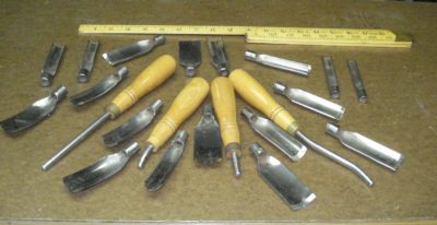
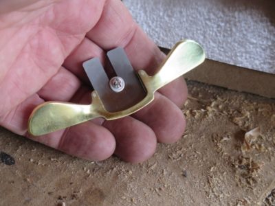
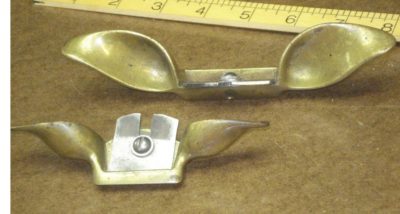
Sculpting Tools – Outside (Spokeshaves)
Virtually all of the outside sculpting was accomplished with spokeshaves, seemingly undersized by furniture makers but capable of really hogging off material when necessary, or feathering a finished surface. Patternmakers usually owned and used at least a half dozen brass spokeshaves.
Fillet Irons
Another truth about metal casting and shrinkage is that whenever two surfaces meet at a right angle or anything near, the crisp inside corner needs to be filled with a cove molding to soften the transition from one plane to the other, otherwise the casting will crack at that line. In my experience this cove was established by shaped wax sticks, called fillets, which were purchased in bulk as literal cove moldings in wax. I recall many, many hours carefully heating both the polished steel ball serving as the anvil, and the long wax sticks, then pressing the warmed wax molding into the inside corner using the fillet iron of the correct size.
This set of fillet irons even came with a scribed pattern block for making scrapers for each iron.
If it went well there was very little scraping afterwards to achieve a perfect inside corner, other times required some shaping with home made scrapers, one for each size of fillet.
Fillet Cutters
In the days before my time in the foundry fillets were cut from the edges of very thick pieces of leather using fillet cutters to create the roughly triangular fillet. These tools would be pulled across the edge of the leather sheet, usually along a straightedge, resulting in a cove-ish strip of leather to use as the fillet. These leather fillets were applied using glue and brads, and the whole assembly was finished by heavy burnishing with the fillet iron. I never had to use this method but since I have a set of the cutters and live in cattle country, come the zombie apocalypse I will be ready.
Core Box Planes
In the Golden Age of Foundries there was probably no bigger component of the industry than that of making pipes. Think about the civic infrastructure whether on a single building scale or a national scale. It was all made from or connected with pipes or pipe-like elements. Making an outside sand mold to cast pipe-ish shapes is no big deal, all the expertise was applied to the problem of making a sand mold “core” to establish the cylindrical hollow insides. For that process a special “core box” had to be made for each unique casting. Often the shape of the box was achieved with core box planes, of which there were many varieties.
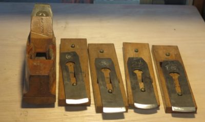
Some looked more akin to a set of hollows-and-rounds,
others were similar to the H&R set but instead of full body planes they had a single body with interchangeable soles and irons,
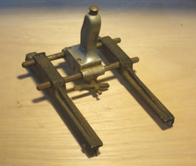
and undoubtedly the weirdest ones were metal frames with notched outriggers to ride on the outside of the core box and were equipped with ratcheting rotating cutting arms that advanced a few degrees around the compass to complete the half-core. Oh, and these mechanical core box planes looked suspiciously like a Klingon warship. There is yet a fourth version that is essentially a right-angle sole bisected by the iron, but I do not own one of those. NB – metal casting of almost any kind involves core box work regardless of the shape so long as the casting has a hollow configuration.
Power Tools and Accessories
Patternmaking since the mid-1800s has employed a variety of machines for fundamental work. Included were power planers (I just use my lunchbox planer but if I did lots of patterns I would get my Mini-Max 14″ combination machine up and running) that could quickly and precisely dimension stock to the peculiar measurements required especially for stack laminated patterns, tables saws, disc sanders and oscillating spindle sanders to allow working to the middle of a cut-scribed layout line at a precise bevel angle usually 2-degrees.
If you follow my trek down the metalcasting road you will see all of these tools demonstrated over time. Well, maybe not the core box planes as I have little intention of casting large pieces of iron pipe.
Stay tuned.
PS I was wondering if I should make a start-to-finish video on metal casting, but I gotta get the Gragg video done first.
After air abrading the two block planes in preparation for their becoming Christmas gifts for my son-in-law, I re-flattened the soles and sides with a finer grit abrasive draped over my granite block, I think it was 120. I taped off these new surfaces and sprayed the planes with gloss black enamel then set them in the window sill to dry really hard, rotating them daily for a couple weeks to make sure the sunlight got everything as cooked evenly as possible.
Removing the tape and sharpening the irons to a mirrored edge that could remove gossamer wisps of wood, oiled every place that might need lubricating, they were ready to wrap as stocking stuffers.
Rehabilitating then gifting block planes is a great way to introduce someone to the experience of a high performance tool.
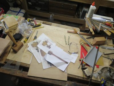
With the decks finally cleared, well mostly cleared at least enough for me to get going down a path whose map has been known for several years, I gathered all the reference materials needed to make the casting patterns for the bronze heads of the HO Studley infill mallet. In addition to the detailed measurements I made when examining the original while assembling the book and the exhibit of the tool cabinet and workbench I had some additional resources. First, as I have mentioned previously, are the hundreds of photographs. Second are the set of silicon rubber molds I was allowed to take from the original. Third, I move forward with the encouragement of the owner of the tool collection itself; I contacted him when the idea for making replicas was first coming into focus. He was enthusiastic about the idea and I believe very appreciative of my consideration in asking his permission. He is indeed a very conscientious historical steward and as I have stated explicitly, he is exactly the right owner and caretaker for this treasure.
In many respects the first two items are combined as I have noted the detailed measurements on the detailed photographs.
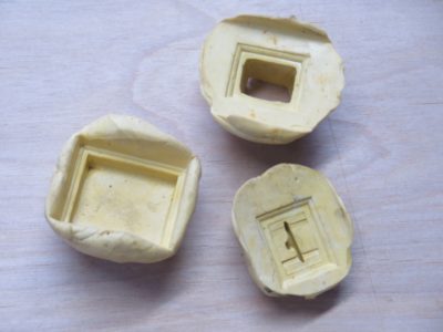
But even detailed images and numbers are not the same thing as three-dimensional representations of the real thing. Taking the silicon molds I made several study castings in wax so that I could more faithfully represent the original in my own pattern modeling. Given the dimensional inertness of the molds and the wax castings made from them I can get truly precise measurements and relationships from exact representations of the mallet head itself.
Time to set up a dedicated space, get my tools and go to work.
NB — I cannot recall if I ever wrote about this on the blog. If not, fine. If yes, you get to read it again.
As I am in the midst of pattern work and prototyping for producing replicas of the HO Studley infill mallet I have been using my retinue of patternaking tools, which naturally draws my memory back to the day 15 years ago when I responded to an ad in Craigslist; I used to scour the Tools section regularly.
The ad was, to say the least, terse and enticing.
Fine woodworking tools. call 703 *** ****
That’s all. Fine woodworking tools. I called, and the fellow’s location was just off I-66 and since I was heading out from Mordor for a weekend in Shangri-la the following day, we arranged for me to come to his home to check it out. I arrived with all the cash in my Tool Acquisition Fund ($400) and he ushered me into the basement room where the tools were.
As we went down the stairs he said “I’m not even sure what all of these tools are, but my Dad was a patternmaker in the Houston shipyards and I am moving into a smaller townhouse on Capitol Hill and just need to get rid of stuff.” Even before we reached the bottom landing my heart was racing.
You see, ever since Mrs. Barn and I got married (40 years next month) and I left the pattern shop for us to go back to college, she was getting an MS in Plant Pathology and I was giving undergraduate coursework a third and final try, I had been looking for tools from the patternmaker’s kit to add to my own. My time in the pattern shop as extraordinarily formative, it was where I learned the definition of “precision woodworking” and practiced it probably more than at any point in my life.
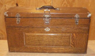
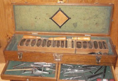
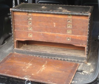
And there it was, a more complete patternmaker’s tool set than I even used in the foundry pattern shop, residing in a pristine but vintage Gerstner patternmaker’s tool chest.
As he opened the drawers the seller said, “I don’t even know what this stuff is, can you tell me what it is?”
For over an hour I walked him through the case’s contents, describing what each tool was. Admittedly the set of orthopedist’s chisels made me scratch my head a bit.
Then came the moment when I asked him what he wanted for the collection. Remember, I had $400 available for the transaction.
“I don’t know,” he said. “What is it worth?”
I replied, “Well, here’s the good news and the bad news. The good news is tool set is incredibly complete and probably worth something like $2000-3000 at least. The bad news is $400 is all I’ve got.”
I was not going to cheat him out of a family heirloom.
I thanked him for the opportunity to browse through his father’s tool chest, which included even his union card and dues account book.
“Someone else will come along who can give you a fair price for this, so just wait for them to call you,” I said.
I left and drove to Shangri-la with mixed emotions. On one hand it was a terrific opportunity to re-live a foundational period of my life, but on the other I really did have a fixed budget of $400. I would never draw money out of the family budget to buy this so I knew that the opportunity was gone.
Two weeks later, much to my surprise he gave me a call. “You were right,” he said, “I got a lot of interest in the tool set. But everybody is trying to chisel me on the price, and that really p!$$e$ me off. So if you can pay $400 and promise to keep the set together and use it for patternmaking, come and get it.”
I picked it up the next evening and he held back only two tools which were too valuable to include in the bargain; a 36″ Starrett Vernier gauge, and a 36″ Starrett bevel-gauge rule, the kind with the 2″ wide scale.
Over these years I have fulfilled my promise and kept the tool set intact and used it for patternmaking work, including the ongoing Studley mallet head project. The only thing I have done is to disperse some of the tool collection into a companion Gerstner patternmaker’s tool chest, a fairly unusual form acquired at one of the MJD auctions.
I did not conduct a detailed inventory and valuation for the set, it is worth whatever it is worth and my heirs can deal with that in thirty or forty years. The only exception was that I must admit to checking on the tool cabinet itself. At that time a vintage Gerstner Patternmaker’s Tool Chest in excellent condition, which this was and is, was around $800.
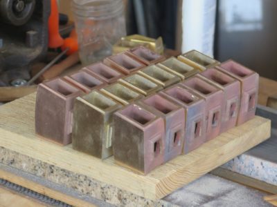
As I move forward with prototypes for producing my line of HO Studley mallets I am aided by a number of different assets. For starters I have in hand almost 20 of the castings from Bill Martley, in a variety of alloys, to work with in taking the rough metal castings to a point of “finished” that I would feel comfortable in providing to interested customers.
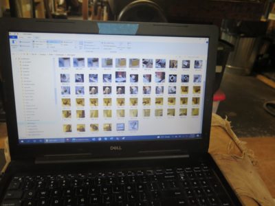
Second, I have a boatload of photographic images of the mallet from about every angle possible (it might seem adequate to have several dozen images, but they are never enough). Reviewing them does make me reflect on the unbelievable resource residing in my compewder; between my images and Narayan’s images I have almost 7,500 pictures on my hard drive .[As a snarky aside, I note that on occasion someone on the interwebz requests (or worse, demands!) that Narayan make all the high quality unpublished images available on-line for free, somehow not registering the facts that 1) the images are the creative property of Narayan and/or Chris, and 2) the images are the result of an investment of (literally) tens of thousands of dollars. If you have ever expressed this sentiment, grow up. — DCW]
Third, a topic I will address in a later post, I have several molds made directly from the original mallet.
Finally, and perhaps the strongest impetus foundational to this project, I have the enthusiastic approval of Mister Stewart to proceed with my effort to make replica mallets because, and I quote, “People should be using this mallet.” That endorsement is a great encouragement to me and I will produce a tool and make it available only once I am proud of it bearing my imprimatur. At some point very soon I will embark on designing the logos to be stamped or engraved into the mallet itself.
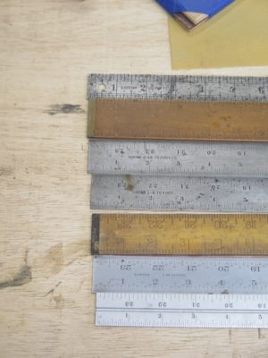
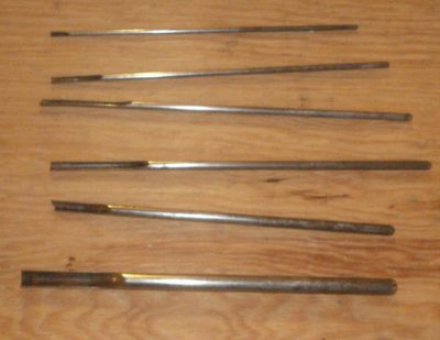
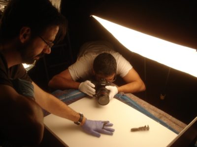
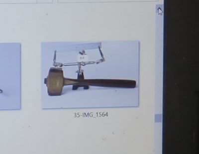
During the many episodes of us examining and photographing the tool cabinet and all its contents, one of the first projects Narayan and Chris conducted was to take “study shots” of every tool so that I could use these pictures as pneumonics for my own work in constructing the book. A second exercise was to formally photograph every tool with a scale included in the frame. Though a standard tool for documenting artifacts in the museum/conservation field from whence I emerged, it has never been more valuable to me than it is right now. Since my documentation for the mallet was not infinitely complete I still had a number of minute details I needed to establish in order to replicate the tool. To cross electron beams with Roubo, I wanted my replica mallet to be accomplished “With all the precision possible.”
Thus the images with the scale in the frame are my “go to” tools for making sure I get the details exactly right. I can fiddle with the file to make sure the printed image is precisely the size of the original artifact, but it is much easier to simply employ the tools of photogrammetry to the task. Although I believe software packages like Sketch-Up do this automatically, I am old school having learned classical photogrammetry in Architectural History classes back in the 70s. Once again the learning of the past solves the problem of the present.
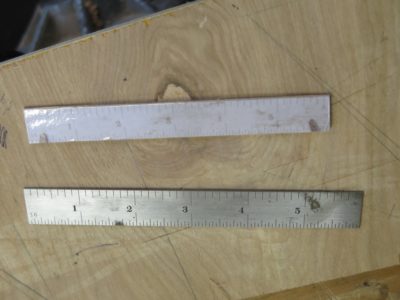
The top scale is one made from cutting out the photograph, the bottom scale is a 6-inch rule from my machinist’s tool kit.
Printing out one of the pictures representing the orientation I needed to make the handle (made from dalbergia, just like the original; I do not have much dalbergia so I might switch to swietenia mahoganii or another tropical hardwood at some point) with the scale included, I simply cut out the scale and used it to measure all the critical dimensions. As you can see the photographic representation of the scale differs greatly from the true scale, that difference is irrelevant because the image of the mallet itself is exactly the same scale as the photographed scale.
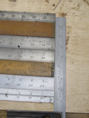
This exercise of using a “wrong sized” scale may be disconcerting to some, but it was the daily order of business when I was a patternmaker. The patternmaker’s tool kit includes a variety of rulers called “shrink scales.” These modified rules are used to lay out and construct a pattern to be used in making the molds for metal castings, and since each metal alloy shrinks a little bit when it solidifies the precise size of the pattern must reflect that reality.
At this point, especially as I create the handle, photogrammetry is more than a mere tool. It is the irreplaceable element.


Recent Comments