
I was mighty pleased with myself when the bench was finished. It was easy to move, easy to set up and take down, good and sturdy with great clamping. Clearly, I had solved all the problems which led me down this path in the first place. However, a little use of the bench showed me that reality was slightly less idyllic.
Unfortunately, its lightness (55 pounds) which was such an asset in my master plan for the “perfect portable bench” was also a big liability once the bench ceased being mobile and was set up as a work station. The bench was so light I couldn’t really work it hard without moving it or even knocking it over. I had to figure out some way of weighting the bench while in use. My “no loose parts” vision was about to bite the dust.

Fortunately, the solution was as simple as building two thin (approx. 1 1/8″) torsion boxes to serve as shelves resting on the crossbar of the end/leg units on either side of the folding bracket, and which could be attached to the underside of the benchtop when not in use. By putting all my tools and supplies on the shelves, the bench now had enough mass for my use. It still wasn’t heavy enough for general cabinetmaking, but it was more than adequate for restoration.

Then a second problem cropped up. The working height for flat-ish or small objects was great, but setting chairs or case pieces on the bench raised them too high. For these taller pieces I needed a lower work surface which would still fit my ideal of lightness and strength. I could have built a lower version of the bench, but instead tried something different. This time I fabricated a torsion box about the same size as the bench top which would fit on a pair of small, low trestle horses. These trestle horses were made from lighter than normal elements, for example the main components were 1″x 1″ and the crosspieces 3/8″ thick.
Some minor modifications to generally employed designs yielded another light, strong and stable unit. By making the top bar of the horses removable, each post of the trestle could then become a tenon. Constructing the torsion box in such a manner that the bottom side had openings to function as extensions to the mortises already incorporated into the grid fitting the tenons of the sawhorse posts, the pieces fit together as a small worktable suited perfectly for holding taller pieces at a more comfortable height. While this new unit was not as “neat” as the workbench, it solved the problem. It also provided more flexibility than simply building another, lower table/bench.

This saga does not end here as I continued working on newer iterations of the concept, but those episodes will be recounted in future Workbench Wednesdays in a few months.
Next week – A derelict salvaged from the trash heap that was transformed into a little jewel.
Building on what I learned from the initial prototype of the portable restoration workbench I charged ahead with a “final” version. I say “final” in quotes because this concept is one I have continued to tinker with even to this day, and a late entry in this series four or five months from now will focus on the most recent one.

For this first final version I used the same structural strategy for the top, modifying the stock weight being the only real modification. On this second iteration I used 3/8″ A/C plywood for both the faces and ribs of the torsion box top rather than 1/4″ and 3/4″ luan for the same purpose on the prototype. Making the box approximately 3″ thick and placing the ribs in a 6″ x 6″ grid achieved a satisfactory result with essentially no change in weight while yielding a stout structure. In fact, I could do some pretty serious joinery and carving on the bench, which I couldn’t do with the prototype.
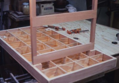
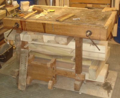
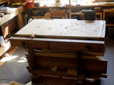
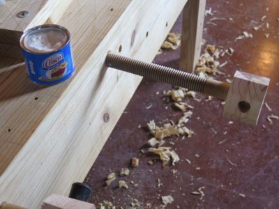
I wanted a large-capacity vise on my bench, but there was no point in defeating my original purpose by building a lightweight bench and then installing a heavy vise on it. The vise(s) I built opens about 12″ and employs aluminum threadstock for the screws, tapped holes in the endpiece of the top, and 2″ x 3″ x 24″ wood jaws. The screws pass through same-sized holes in the movable jaw, and terminate in simple wooden handles passing through holes drilled in the ends.

One pretty dramatic change in this function was to switch from standard steel threadstock to 1-inch aluminum rod stock that I had cut at a local machine shop (I already had the aluminum rod stock in my scrap barrel). It’s been a long time since this project but I recall paying $25 for the job. All it took was to set up the pieces in the lathe and cut the threads with a single pass, along with a single groove above the threads for some retaining collars. I’m guessing it took ten minutes maximum, so $25 for a quarter hour of machine shop time sounds about right. It might have been $25 for each pair of screws, but either way it seemed pretty reasonable.
My procedure for incorporating the vise into the bench top involved drilling oversized holes in the internal grid but not the added fixed jaw, so I couldn’t assemble the box all at once. I cut my grid pieces and glued them to one face of the torsion box using 315 gram hot hide glue, which was the adhesive employed throughout the project. After laying out for the vise screws, I drilled holes through the fixed jaw (the torsion box end pieces) to tap-out and received the threaded screws. I was unsure whether holes the same size as the aluminum rod stock used for the vise screws would be large enough to allow the screws to go through the grid members, given the inevitable wobble in the screws. To be on the safe side, I drilled larger holes through the grid to a slightly longer distance the desired vise opening dimension. The vise screws would then pass through these openings as the vise was closed. After I was sure the vise was fully operational, I glued the second face on the grid and the top was complete.

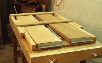
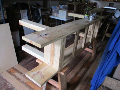
By fabricating simple leg end units with long folding diagonal braces, the problem of too much shimmying parallel to the long axis was overcome on the final bench. The leg units were fabricated from the clearest 2x construction lumber I could find, and the folding braces from 1/4″ x 1″ aluminum bar stock with 1″ x 1″ aluminum angle stock for the mounting brackets. The slightly heavier face plywood made it easy to screw all these elements to the underside.


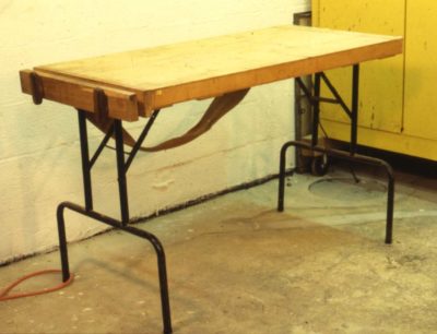
The leg units were not installed symmetrical relative to the short axis, but rather were off-set by half the leg width so they could fold up next to each other rather than on top of each other. This way, the table could become a remarkably compact unit which needed absolutely no assembly or disassembly; it could just be folded up. Following final assembly I added a snap-on strap for carrying the bench like a large suitcase. By throwing the strap over my shoulder, I could easily carry the bench for long periods of time and maneuver it through pretty tight quarters.
Next week, some accessories.
Because of the rigidity and (light)weight requirements for the portable restoration workbench, the obvious choice for the top was a torsion box, the construction of which was virtually identical to those described in the woodworking literature. My first attempt used 1/4″ faces and 1/2″ ribs of luan plywood. The weight and rigidity were good, but the working surface of luan was a little too fragile. Nevertheless it was a confirmational “proof of concept” exercise.
My first step was to make a simple torsion box as a test run. It was near-perfect as the top and working surface. I faced this prototype with cork on one side and plastic laminate on the other, and it remains in use in the shop to this day almost thirty years after being made.
Concept One – check.

My first inclination was to make a trestle base for the bench, but considering my master scheme this idea had some significant drawbacks. While easy to build and assemble, the knock-down/assemble/disassemble trestle requires multiple parts, and one of my stated intentions was to not build anything that required keeping track of lots of pieces. Instead, on my first attempt I tried using a pair of commercially available tubular-steel folding-table legs. These worked fine along the short axis of the bench but weren’t stiff enough along the long axis because of short diagonal braces. Though a good concept, this shortcoming and the unnecessary weight of the steel legs made it a non-starter as a final option. Even with those hefty legs the unit weighed in at only 55 pounds, well within the limit I wanted.
Concept Two – check.
As for the vises I simply used pieces of 2x stock cut to match the dimensions of the ends of the top combined with 3/8″ steel threadstock from the hardware store and some wood handles epoxied onto the ends. Again the concept was successful but the fine-ness of the thread made the vises tedious to use.
Concept Three – check.
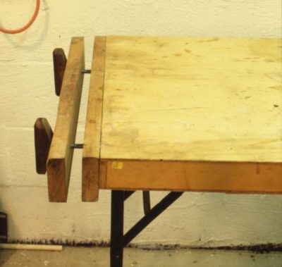
Finally I threw on a piece of upholstery webbing to serve as a shoulder strap so the folded bench could be carried and maneuvered easily. That concept was an absolute winner. Throwing the strap over my shoulder it was a breeze to navigate the twisting rabbit trail to a work site.
As a final test run I took the prototype to a job and it worked out just fine within the confines of the limitations enumerated above. With what I learned from this it was time to move forward with a final iteration.
Check, check, check, and check.
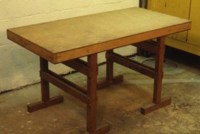
By the way, this bench is still in use but as a food preparation station for the barbecue.
This is the next of an occasional series on the workbenches I’ve built over the years. — DCW
=======================================================
By the late 80s not only was my young career at the Smithsonian humming along but my outside work for private clients was keeping me as busy as I wanted to be. An awful lot of those projects were “on site.” Whether the client was a private collector or an institution, with increasing frequency I was working at their location. There are many reasons for this; cramped quarters at home, the legal liability of transporting very valuable objects, the cost of renting a truck and hiring someone to help out (I usually work alone), etc. Regardless of the cause I often found myself working in unfamiliar, and usually unequipped, surroundings.
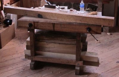
Thus, several times a year I would move lock, stock and “workbench” (saw horses and plywood or door) to a new location, a truly onerous activity. One project in particular, in a museum’s sub-basement down three flights of a spiral staircase, provoked me to build a high-performance lightweight folding workbench that remained in use for many years before retiring to the deck o serve as a serving table when I cut back on my on-site work. I have improved on both the design and execution of the bench in recent years but for now I will stick to the 1989 prototype and the 1990 finished bench.
This growing commitment to on-site work justified a little investment of my time to work out the problems inherent in occupying space that was not my own. In the end, that process of finding a “better way” resulted in the design and fabrication of a new workbench and some companion accessories to make the task of working in a portable studio more manageable and productive.
What did I want?
The only thing I was sure of was that my sawhorse and plywood routine had to go. But what arrangement was to take its place? Being a lazy fellow, my first actions were to look around at the market to see if any of the available “portable” workbenches were suitable.

I discovered only two real options; a small, pseudo knock-down version of the European-style butcher-block-top bench, or a Workmate. I looked at a couple of the former, and own one of the latter. I found the portable Eurobenches to be too small and unsteady for my use (and quite frankly, too “cheezy”). In addition, they still weighed-in at around 100 lbs. Since I would have to carry it by myself, it was simply too heavy. I tried my Workmate on a couple of projects, but it wasn’t exactly what I really wanted because it was too top-heavy and the work surface was too small. My search for a manufactured bench to suit my needs wasn’t exhaustive, but nevertheless, I decided to design and build my own portable workbench.
The process of procuring a new, high performance portable workbench began with the question of exactly what I wanted out of the bench, regardless of its source. When I decided to make my own, I had only to review those requirements and build to fit them. Back to the original question, what were my specifications for the bench? The answer was simple; 1) the top had to be perfectly flat and about 2’x 4′ (any smaller and I might as well stick to my Workmate, much larger and it would have been unwieldy for some of the pathways I had to traverse), 2) it had to have a vise sturdy enough to take a modest beating, 3) the bench had to be very light, compact, and easy to set up and take down because I didn’t want to have to assemble a kit each time I moved, and 4) it couldn’t cost a fortune in time or money to acquire. It was also important to remember that the bench wouldn’t have to stand up to immense weight or stress, since the pounding necessary during general joinery was rarely required in a conservation project. Any particularly heavy work dictated by a specific treatment would still have to be done at home.
The bench I ended up with was not an example of exquisite handworked joinery, but it did require precise machine woodworking techniques. The bench shown here is my second version and still not perfect, but it is completely functional and does satisfy the requirements listed above. It might be bragging but I think it remains the finest high performance portable bench design I have encountered to date.
The top is the right size for my needs at the time (although it could be made any size), and contains a pair of 24″ twin-screw face vises at the ends which opened about 12″. The bench folds up into a compact unit weighing only about 50 lbs., making it extremely easy to move about. In fact, the lightness presented another problem which I will describe later on. The long diagonal braces, which fold with the legs, provide plenty of stability to the bench allowing even more aggressive cutting and pounding than I had hoped for. In addition, I built several accessories which enhanced my capabilities for restoration on-site. Finally, in terms of both fabrication time and materials cost, the bench was very inexpensive. It took about six well-planned hours and $75.00 worth of materials to build, plus about $25 of machine-shop time (in 1990 dollars). You can fancy it up as much as you want, but you can have the basic unit quickly and inexpensively.
Next time — the “proof of concept” prototype
When making traditional-ish workbenches one of the considerations is making the holes for the holdfasts. I might have said “To holdfast or not, that is the question,” but in my experience a woodworking traditionalist either decides to incorporate holdfasts from the start or comes around to using them eventually.


As a general rule the hole for the holdfast is a smidge bigger than the shaft of the tool so that when the top is pounded to induce flexing tension the holdfast grabs the bench top firmly. As a practical matter virtually all of the holdfasts I know are available now use either a 3/4″ or 1″ hole. Getting the holes perpendicular to the bench top on two axes can be a nuisance some times, and in the past I have made a couple of drilling jigs on the drill press. However, over time both of these versions became wallowed out and somewhat less than fully helpful.
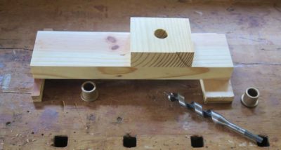
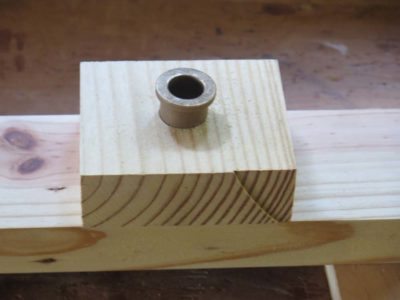
After returning from Arkansas where my older jigs got a serious workout I set to making another more robust and precision jig for fitting the Gramercy Tools holdfasts that I am so fond of. My main modifications for this were to lift its base up off the workpiece with plywood feet to provide exit for the chips, and bronze bushing sleeves fitted to the 3/4″ drill bit.


I drilled the hole for the O.D. of the bushings, then epoxied them in place. Finito.
This is the first in an occasional series on the dozen-plus workbenches I have. These are presented roughly in the order in which they entered my orbit. — DCW
================================================
1984 was a monumental year for us, as we finished up our time in college (my third try was a charm), both got jobs we wanted (in the same town!) and bought a little house just outside the Mordor Beltway on 3.7 acres to expand (the house, not the property). Though I still had one more year of evening classes to graduate life was beginning to settle down from the maelstrom of a heavy college load and workto pay for college occurring simultaneously (I refused to borrow money for college). I was a poor role model for my daughters’ friends, I took 14 years to get through college.
By late 1986 it was time to fashion a workbench for the small work space (10′ x 22′ x 6′-3″) I had carved out in the basement for household and furniture conservation projects for private clients who wanted to throw money at me. We wanted to get ahead as much financially as we could before our family started. Oops, too late. Daughter #1 arrived that autumn. Nevertheless it was time for my first real purpose built custom-made-to-my-specs workbench. Until then I’d had “make do” with whatever I could scrounge together.

The process of bench design weighed several competing and complimentary considerations. The manner in which I resolved and fulfilled them resulted in a workbench that is my third child.
First, I had very limited space, especially when you consider the amount of machinery I had stuffed into the space. A unisaw, a 12″ radial arm saw, a 14″ combination planer joiner, standing drill press, large air compressor, etc., were all taking up residence there, along with a full-sized explosion proof solvent cabinet for my finishing and conservation supplies. There was no way I could afford the luxury of an 8-foot patternmaker’s bench with an accompanying assembly table, which is what I’d had in the foundry, nor an 8-foot Euro bench like the row of them in the conservation studio at Winterthur and the Smithsonian, or the English wall bench from the Dominy shop. I would be lucky to get four feet of bench in my basement workshop. In the end the bench’s overall dimensions are 48″ long, 33″ deep, and 35 inches high.
Second, I was not going to be making much furniture in the basement, or anywhere else for that matter. As it turned out the few pieces I did make in the coming years were assembled either on the front porch or out in the 15×25 barn-ish shed we had for the lawn equipment. It wasn’t so much of a footprint issue as it was headroom.
Third, I was very much enamored, and still am, with the concept of the torsion box structure for workbenches and table tops. I’d seen Ian Kirby’s version and really liked it. Not the MDF part, but certainly the design simplicity for his workbenches. I had not become persuaded by the planarity of the sides for many years yet.
Fourth, an Emmert K-1 vise had become part of my work vocabulary in my years at the pattern shop, and I had subsequently purchased a couple of fine vintage ones and was going to design the bench around them, or at least one of them.
Fifth, though I was not a chair maker and would never really become one I was attracted to the expanse of large twin screw face vise often found in their shops.
Finally, I was not the aficionado of hand-work that I have become so keeping hand work to a minimum was desired.
I purchased a pile of 12/4 and 8/4 white oak and a couple sheets of 3/4″ birch plywood and got to work. Unfortunately I have zero pictures of the building process, all these come from much later.
Up until this time my “workbench” was a salvaged 36″ wide solid core door sitting on a pair of sawhorses, which makes for a lousy workbench but a great assembly table.
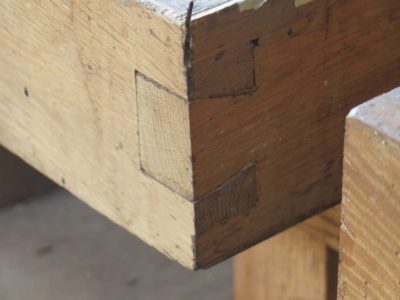
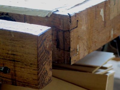
Cutting the 3/4″ plywood on the table saw I constructed the 24x48x5 torsion box bench top, fitting it into a rabeted perimeter of 8/4 oak dovetailed at the corners.
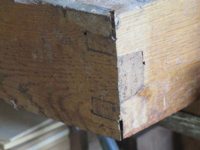
These were my first man-sized dovetails and the inexperience shows, especially in the corners where I laid out and cut the joint adequately but inverted the angles. Think of a dovetail joint where the tails do not spread but rather taper at the same angle and you get the idea. It’s not terribly made, but it’s not proper either. It remains a constant reminder to be more careful and make sure I am envisioning things correctly. I am neither proud nor dishonored by these corners, they were an honest representation of my joinery skills 32 years ago, and emphasize the different skill sets of a conservator and a furniture maker. I have improved in the intervening years.

This top went over a simple trestle-and-stretcher base that was half-lapped on the radial arm saw and bolted together. To attach the top to the base I drilled and screwed threaded brass inserts into the top and drilled the corresponding holes in the trestle top crosspieces, bolting them together. The general assembly scheme has worked for the intervening years without a fuss. Every now and then I crank down on the bolts when anything loosens up, but the unit has remained remarkably trouble-free.
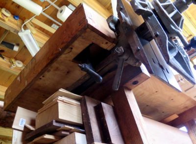
It was in installing the Emmert that I realized a couple of mistakes that I could have corrected, one a nuisance and the other a fundamental problem I will eventually correct. For starters the 5″ thick torsion box was way too thick for the Emmert configuration and I had to cut through the torsion box skin and ribs in order to make it all fit and work. Fortunately this did not weaken the top appreciably.
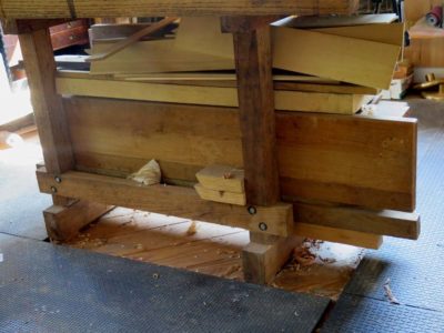
But another miscalculation has required compensation ever since I built it. Rather than fit the Emmert between the trestles I designed it to be outboard of the trestle at that end, rendering the whole thing unbalanced and susceptible to tipping when under load. I’d thought that the weight of the 12/4 & 8/4 oak trestle structure would be enough, but I was wrong. I really should have made the trestle longer to allow the vise to be installed in between the two ends. I finally settled on something resembling a solution when I turned the bench base into a lumber storage unit. The addition of several hundred pounds of counterweight does the trick, but a third trestle (or moving the current one) outboard of the Emmert would be even trickier.
On the long side opposite the Emmert I added a full-length twin screw face vise using hardware I think I bought from the bargain bin at WSJenks, a famed DC hardware store. The movable jaw is 2-1/2″ x 5″ x 48″ in white oak with 32″ between the screws (zero flex), and it is a fixture that is used pretty much constantly.
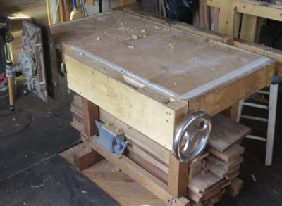
Years later I made a wagon-wheel vise for the side with and aligned with the inner jaw of the Emmert, a project I chronicled in a Popular Woodworking article. It is a useful addition, but since I have so many other options for the same function it does not get used much these days.
While not without flaws and limitations, this bench has remained my “go to” work station for more than three decades, and is only now grudgingly giving up its status as my one and only workbench. It still gets my time and energies every day.
My name is Don and I have a lot of workbenches. It’s neither a confession nor problem, it’s just a recounting of fact.
No sooner had I returned home from Arkansas and delivered Bob’s bench to him (it was the prototype for the bench we built 7x at the workshop) I noted its absence from the barn and immediately set about to fill the void.

The finished unit went into the classroom, where I am trying to replace any sub-standard benches with first-rate ones. I’ve got one more to go, maybe two especially if you count restoring a vintage one. I’ve got about another hour of work to install the twin screw face vise on this Nicholson and then I’ll move on to something else.
It occurred to me that it might be amusing to udertake a chronological recitation of my entire extant workbench inventory, so beginning soon I’ll try to present “Workbench Wednesdays” (am I a marketing genius with slogans or what?) giving some history and a review of my benches (including the crapdoodle ones if they have not been “decommissioned” in the wood stove) until I get through the list. As near as I can tell this will take several months of Wednesdays to complete.
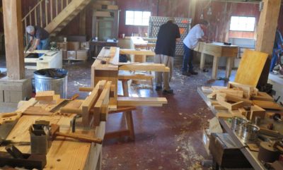
On the syllabus for Day 2 was to finish up the workbenches quickly and get started on the initial pair of pratica, namely the winding sticks and the planing stop. But in the lull of battle preceding the gathering of the students I reveled in just walking around, admiring their productivity yesterday.
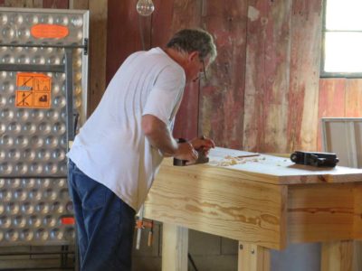
The benches soon received their finishing touches of holdfast holes and threaded aprons to accept the screws for the vises. I learned after the fact that a good drilling jig would have been very helpful for these holes. A few of them were slightly off kilter, and a good jig would have saved a lot of headache in the end. I’ve already got the design in mind and will fabricate it as soon as I get home.

Soon the holes were drilled and threaded and the screws lubricated and tested in them.
The double-thick jaws were laid out and drilled with a drill press that was brought over from the shop and the vises installed.
After this the Moxon vises were a cakewalk.
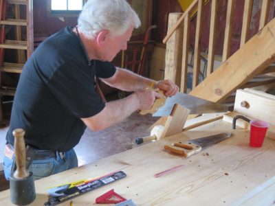
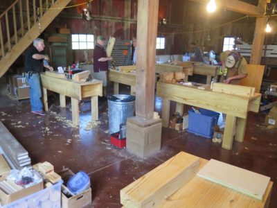
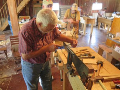
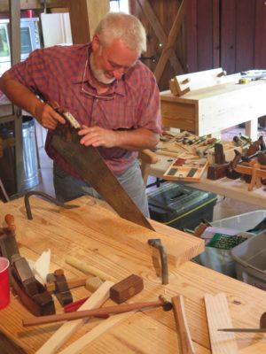
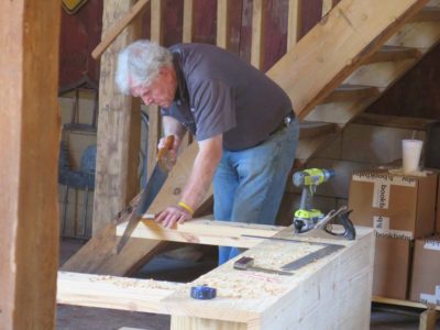
The benches were then given their first real workouts with the resawing, ripping, and crosscutting of the pieces for the winding sticks and planing stop. All variety of saws were employed, with my giant c.1800 two-man frame saw the the new Bad Axe version receiving great acclaim.
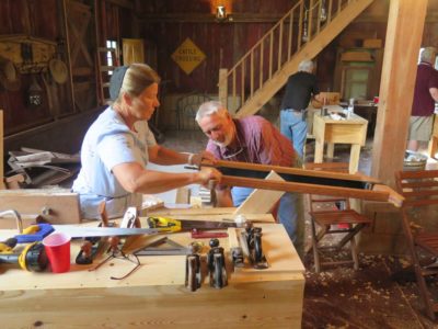
One of my treats for the day was giving Cam a lesson on saw sharpening. He’d finished up his work in the metal shop for the day and dropped in to see what we were up to. Being a skilled metal worker Cam took to it like a fish to water and the results were gratifying.
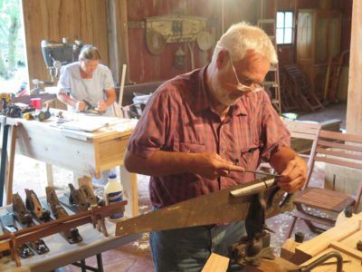
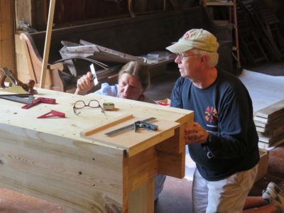
This is one of my favorite images for the week, with husband and wife working alongside each other in their own tasks. A profound model for us all.
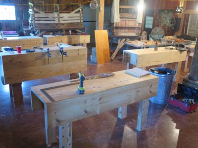
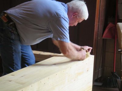
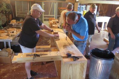
The agenda for Day 1 of the workshop was ambitious. We first met for an introductory time and a review of the expectations and projects of the week. I won’t say there was disbelief at the list of things we were going to do, but I could sense some skepticism. Especially that part about everyone building a complete bench on Day 1, a heritage tool that would be up on its feet by the end of the day and ready to be put to work for Day 2.

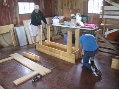
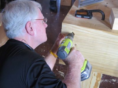
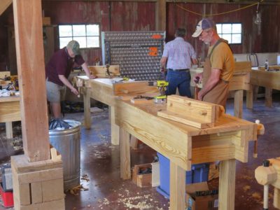
And that is what we did. I described and demonstrated the process of building the Nicholson bench and everyone got to work, with cooperation and fellowship abounding. All the 2×12 SYP lumber had been pre-cut so it saved a fair bit of time and allowed for the students to work more efficiently. As did the use of battery powered drills and decking screws.


Before lunch we had at least a couple of them up on their feet for the first time. There are repeated up-and-downs with these benches as many of the subsequent steps occur (or should) while it is laying over on its side.
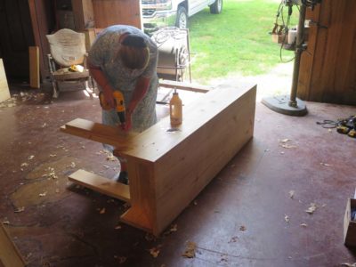
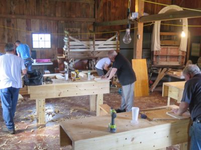
After lunch at Jane and Cam’s restaurant, the best one in the region by far, things got hopping as the tops were added followed by the second lamina for the legs going into place with decking screws and glue.
The front edges of the tops were planed flush with the front aprons and folks got the sense that a real live pile of workbenches was about to happen.
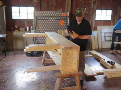
Before long the legs were being trimmed to length and the tops flattened, Round One. I recommended that everyone wait until next summer for the final flattening of the tops.
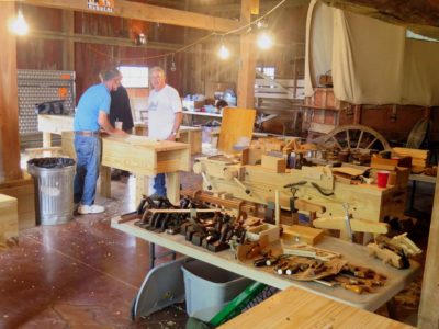
Here are a final few pictures from the day as holdfast holes appeared in great abundance, making the benches fully functional even before the twin screw vises and Moxon vises were completed the following day. It was such a roaring success that it resulted in total buy-in from the participants for the rest of the week.
The final large scale undertaking for the trip to teach in Arkansas was to make the wood screw sets for both the face vise and the Moxon vise, enough for ten benches. There was nothing special about it other than the scale of the work, in total I made 20 long screws and 20 short screws.
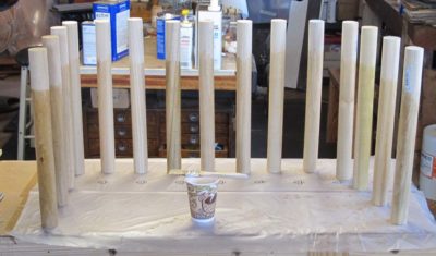
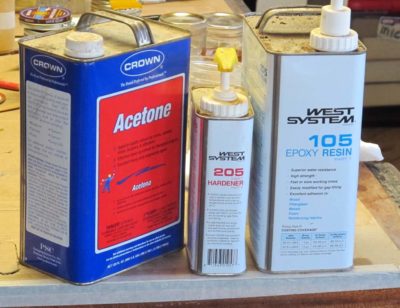
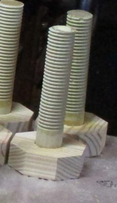
Again I doused the tulip polar dowels with acetone-diluted epoxy and set them aside, moving on to the octagonal knobs.
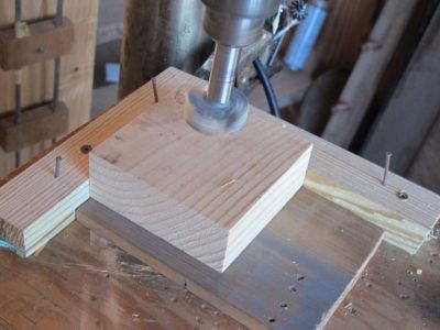
I ran off the 60 squares needed for the knobs (the face vise hubs were double layers) then moved to the drill press to punch the center holes into which would go the threaded dowels.
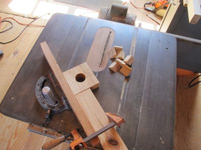
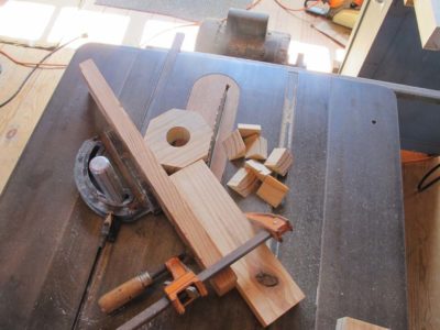
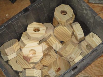
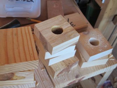
Once I had the requisite pile of holed blocks I returned to the table saw and octagonalized them. I must say that drilling the holes first made it a lot easier to handle them in this process, there was always somewhere to grab to hold them firm against the fences for the miter cuts.
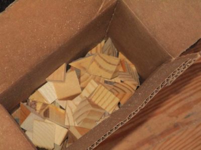
A pleasant by-product was a box of glue blocks from the off-cuts. I’ll set that aside and will no doubt use them over the coming months and years.
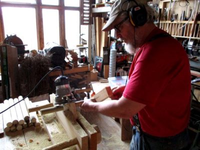
I dealt with the long screws a little differently from the short screws at this point. This had to do with the arrangement of the Beall thread cutter. With the long screws passing through a double thickness of stock for the movable jaw I could get close enough to the thread cutter for the threads to work fine by making a split handle to hold and turn them. This was not true for the shorter Moxon screws, so I fed them by using a small plumbers wrench as a grip to get the threads far enough toward the head.
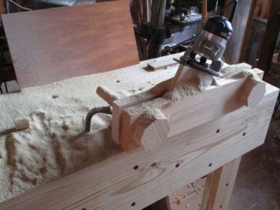
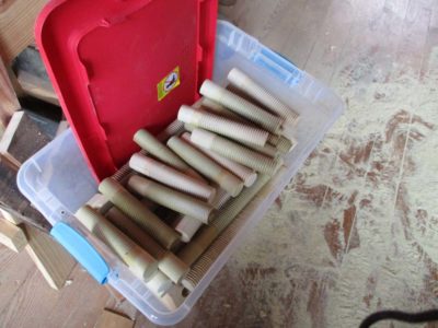
Off to the thread cutter, where a couple hours of concentration and labor ensued. Before long I had a large tub of thread stock.
I glued the knobs on them using yellow glue.
At this point the shorter screws were finished. As for the longer screw’s doubled knobs I trued up the octagons with a Shinto rasp and drilled the pass-through holes for the handles they were finished, too.
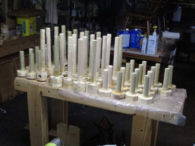
Two full tubs of vise screws and it was time to move on to the next thing.

Recent Comments