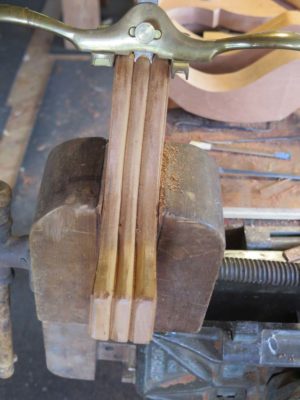
With Roubo Joinery Bowsaw Prototype tested in battle and found wanting in the lightness department, it was time to think about ways to reduce the overall weight and bring that down to a point I was comfortable with. As it was now, it was a massive beast that was simply too heavy to use as a one-handed saw for cutting tenons or dovetails.
I rounded all the edges substantially, but that was not enough weight reduction.


I sculpted the tops of the arms, it was pretty but insufficient.

I transformed the stout cross-bar into a diamond cross-section with tapered chamfers providing the transitions. Nyet.
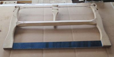
It wasn’t just a smidge heavy, it was a couple pounds too heavy. Achieving any more mass reductions would have been quicker with a new starting point since I had obviously selected the wrong one here. Since Bad Axe had sent me some new plates to my specs, that’s where I went next. We’ll see if 3/4″ white oak stock is up to the task of restraining these plates, or if I need to address this frame again with acres of carving and other diminutions. At the very least, with 3/4″ stock I would start with a 40% reduction in weight, so the idea was promising.
Stay tuned.
When asked how many clamps they have, any woodworker worth their salt usually has two connected answers “1) A lot, and 2) not enough.” Given the expense of manufactured clamps in our age, consider the relative cost 250 years ago when everything was made by hand. I would imagine forging a single functioning iron clamp was the better part of a day’s work.
In part for this reason, Roubo and his contemporaries devised inexpensive, high-performance and practical solutions to the problems of clamping, especially for clamping up panels. I too have followed their lead, and despite having many bar and pipe clamps I find these to be a terrific addition to the workshop. The engravings are petty self explanatory, straightforward enough that I could crank them out in minutes.
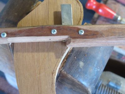
My base stock for these is scrap 2×4, with clear grain if possible. Laying out a series of square holes, off-set from the center line (almost certainly overkill, but then I tend toward overbuilding everything), I punched the 1/2″ square holes through the 2×4 with my mortiser.
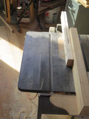
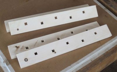
That done I just re-saw the 2×4 on the table saw, yielding two identical halves of one clamp bar set.
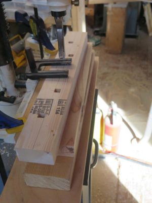
Add a group of squared pins to connect the clamp bars and some wedges to tighten on the panel being glued and you are pretty much done. NB: Before using for actual gluing all the surfaces of all the components should be coated with wax or grease to prevent sticking once the glue dries.
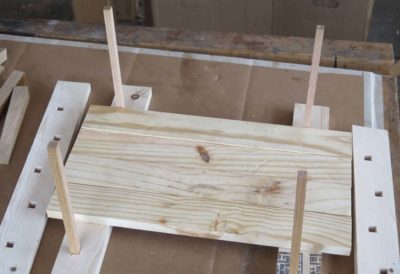
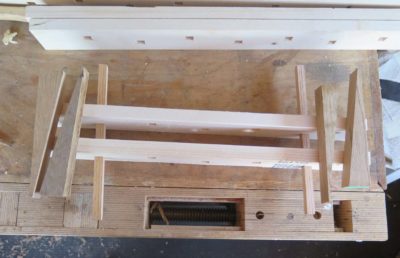
In use I just place half of the bar pair on the bench at each end of the panel assembly and insert the cross pins into the square holes, followed by placing the gluing subjects in place.
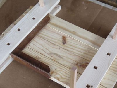
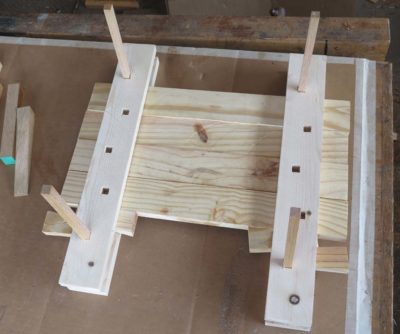
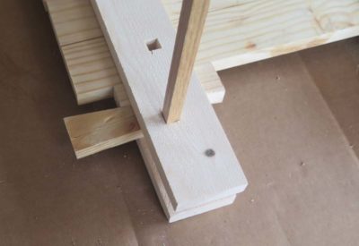
The other halves of the clamping bars go on top and once everything is squared the wedges are driven in to squeeze things together.
Finito Mussolini.
Fortunately for all of us afflicted with terminal toolaholism we are not the first ones down this path of compulsion; we stand on the shoulders of giants who got there first and established well-oiled mechanisms to feed their “needs.” EAIA, M-WTCA, MJD, Superior, all there to provide you with a focus for spending to satisfy the urge (if you sign up for the latter two they will deposit tool listing directly into your email in-box).
Another such group is the Potomac Antique Tools and Industries Association that meets monthly, and once a year holds its mondo crack-house flea market, dealer sales and auction event. Since this often coincides with the Highland Maple Festival back home I can attend only occasionally.
This year was one such occasion, as our guests for that weekend of the Maple Festival canceled and I was free. So off to Damascus MD I went with a little money and a shopping list.
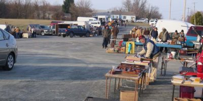

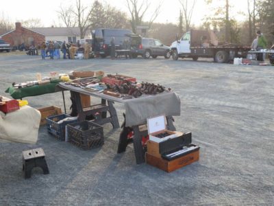
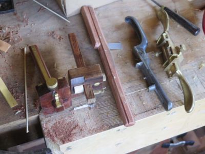
The tool flea market in the parking lot begins around sunrise, or so I am told, I generally arrive about 7.30 and find the festivities well underway.
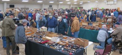
At 9.00 the inside dealer sale opens, and the morning is spent fondling, testing, purchasing, and yakking about tools.
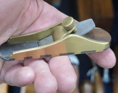
I almost pulled the trigger on this one, but the quality/price point just wasn’t good enough. But next time I will recount the great deals I did make.
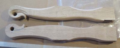
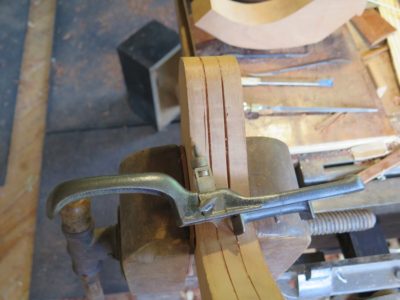
With the stirrup system finalized for anchoring the saw plate it was time to move on to the frame. Armed with some extra-dense 5/4 white oak I dove in. I wanted to make sure the frame was both simple in construction and beefy enough to withstand the stresses of tensioning such a robust plate.

The overall structure couldn’t be much simpler — two vertical arms connected by a crossbar that was inserted as an unpinned mortise-and-tenon into the arms. Once I had the dimensions and proportions where I wanted them I used my mortiser to cut the pockets in the arms and sawed the tenons on the crossbar.


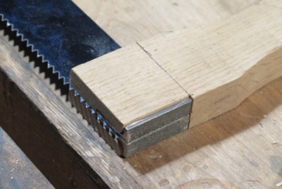
Then I moved on to the housings for the stirrups. It was a simple matter of laying them out against the base of the arm, removing the material so that the stirrup fit neatly, then sawing a slot for the plate to go through.
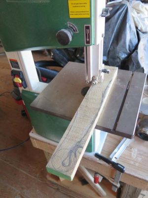
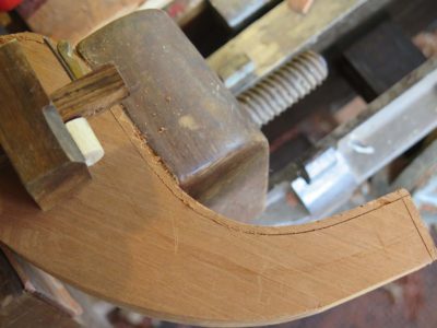
With the arms and crossbar cut to length and fitted together, and the stirrup housing made, I sawed the curved shape of the arms on the bandsaw.
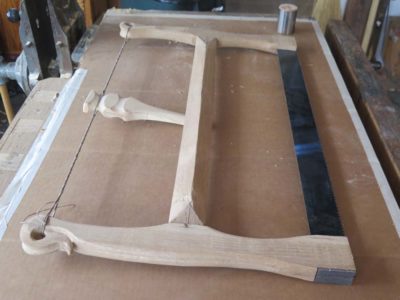
I assembled everything together just to make sure the parts all worked together before moving on. I really was pleased with the manner in which it all fit together. It seemed a little beefy, but I had not put it to work yet. Besides, it is considerably easier to make elements smaller ex poste than to make them larger. It made me recall on of my Dad’s favorite quips in the shop, “I just don’t understand this. I’ve cut it twice and it is still too short.”
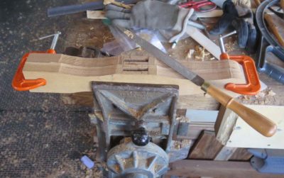
With rasps and spokeshaves I shaped the arms to be more congenial to being hand held. Once it was far enough along to give it a test drive I assembled it completely and strung the top with multiple strands of linen cord for tensioning, found scrap stick (a practice spindle from the writing desk) to act as the windlass paddle, and it was ready for the race track. I’d added a small vanity flourish at the top of the arm so I just knew it would saw like a banshee. I cranked up the tension until the plate twanged like one of Stevie Ray’s guitar strings (before he broke it) and lit into a scrap of wood.
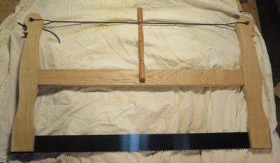
And it did saw like a banshee. Made from concrete. It was so heavy I actually grunted when picking it up to use the first time. Somehow I had to hog off a gob of mass or otherwise it was a two-handed-only tool, and I wanted something that could be used with one hand.

Before I got too deep into making the “bow” of the bowsaw I realized I needed to work out the details of how exactly the saw plate was to be anchored to the bow frame. Given the robustness of the saw plate from Bad Axe and the illustrations and commentary from Roubo I knew this was not a casual thing. The amount of tension required to make the saw plate perform well was considerable given the dimensions of the plate, so the anchors for the plate had to be able to withstand the force requisite for making it function well. And, given the likelihood that any user of such a saw as this might well want to swap out the plate from one utility to another, taking advantage of varying plates that could be available. So, the fitting of the plate to the frame needed to be not only exceedingly stout but also easily reversed or swapped-out.

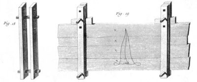
The clue to the preferred manner of fixing the plate within the bow frame was pretty clearly described by Roubo in his commentary to Plate 12. While the simplest method would be to simply drive a pin through the foot of the bow frame and the end of the plate, there was and is a better way. And he tells us how to do it.
There is still another way to attach the blade in the saw, which is to use stirrups, which are pieces of sheet or flat iron that you fold into the form of a “t”, and that you attach to the two ends [of the blade into the stirrup] with a single nail the same way as above. These are then inserted into grooves in each of the arms, which you take care to fasten tight enough to hold them. This method is very good because the stirrups holding the arms from their back sides make full use of the arms’ strength, without which they might split, and you only use one nail to hold the blade at each end because if there were two it would prevent even blade tension, figures 11 & 12.
I took this information/description and started running with a couple of changes. First, the folding of bar stock into the “T” was not possible with the material I had on hand, although it might be fine with lighter steel flat stock like 1/32″ or 1/16″. I didn’t have that (nor did the local fabrication shop) and I was too impatient to wait for some to be shipped to me. Second, the plates supplied by Bad Axe have two bolt holes, which I believe are necessary to house fittings strong enough to tension the plate. Still, I really liked the concept of a “T” shaped stirrup to affix the plate in the frame.

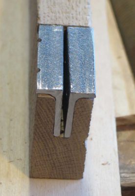
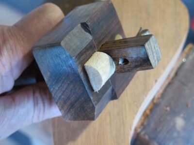
So instead of folding thin flat stock for this purpose (although I am certainly likely to try it in the future with either thin soft steel flat stock or brass, although I like the solution I came up with for other reasons) I sawed some 1/8″ x 1″ x 1″ angle stock I had on hand. I cut the length such that the body of the plate would be fully housed but the teeth were exposed and unfettered.


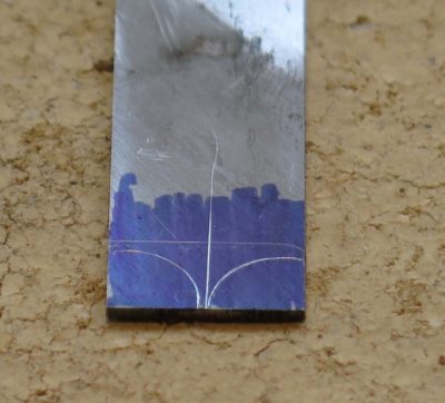
Then I cut off most of one side of the angle stock to reduce the arm of the stock from 1″ to 1/2″ so that when two pieces of the cut angle stock were placed together the configuration would be a “T”. I used the finished plate itself to provide the layout holes into the stirrup “T” plates. One half of each pair of the plates was drilled and tapped, the other was drilled and countersunk to fit machine bolts I had in my hardware stash.

Placing the two halves of the “T” stirrup over the pair of bolt holes in the plates, and screwing in the machine bolts, the task of mounting the plate to a stirrup was finished and it was time to move on to the bow frame (this picture is a bit out of sequence and was intended for another purpose but you get the idea).
One of the many peculiarities of mid-18th Century Parisian workshops and their accouterments as documented by Roubo revolves around the absence of backsaws and panel saws in the tool kit. These were bow saw and frame saw folks, and they used bow saws for any number of functions at the bench including stock prep and dimensioning to delicate dovetail work. As for the panel saw, it was only mentioned in one brief sentence and then only in the context of building carpentry. For whatever reason the French furniture and joinery shops were committed to open frame saws, whether bow saws or sash saws, as their workhorse tools.

Subsequent to my visit to Bad Axe Tools in November and the conversation it sparked about saws in mid-18th Century Parisian workshops, both Mark Harrell and I were noodling the concept of interpreting those saws for contemporary craftsmen. I think we arrived at the same point more-or-less simultaneously, and I suggested the need for exploring bow saw prototypes based on the saw plate for the Bad Axe one-man Roubo-esque frame saws. Mark bit and expressed immediate support. By “support” I mean that he would provide me with some saw plates for me to try out the concept, and would fabricate custom specified plates for me to experiment with.

***A note about such a collaboration: I gladly share my knowledge and curiosities with anyone interested in pursuing the same paths I am on. I’ve made available all the observations, opinions, and documentation I have, including detailed photographs of my own vintage saws, to anyone who asked. In that regard I am not showing any preference for Bad Axe, they were simply the folks who asked me to engage in this exploration.***

Since I already had a Bad Axe frame saw and thus the dimensions of their standard saw plate I was able to begin fabricating a bow saw as close to Roubo’s as possible, or at least as close as I could guess. I grabbed the saw plate, some of the ultra dense 5/4 white oak from my stash (left over from making the Studley bench top replica for the exhibit), and got to work.
The results were instructive.
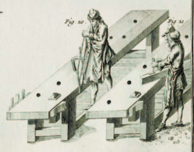
When constructing a bowed or undulating panal or structure, one of the challenges is to decide the manner of achieving the shape. Commonly there are main four methods employed: sculpting/carving from solid slabs, a la bombe’ chests; glued laminations (home made curved plywood); contour- sawn layers or segments glued together in a stack, sometimes called “brickwork”; or coopering, which involves the assembling of long sticks or boards that are isosceles trapezoids in cross-section (“staves”) with the legs of the trapezoid angled such that the assemblage follows a desired curve.
If you consider the forms of furniture common in Roubo’s time, it is clear that there was a need to produce large numbers of curved panels reliably and quickly. This calls for coopering. And, for each individual curvature/radius a unique set-up was required. Roubo presents two distinct solutions to the problem. The first, marked “a” in his drawing, shows a pincer/bar clamp and a group of spacer shims to align the individual staves to assure the proper configuration while the glue sets. This approach strikes me as very finicky, and thus time consuming, to achieve standardized results.
Roubo’s preference was stated unequivocally in his commentary on Plate 102.
Before speaking of gluing curved wood, it is good to enter into the details of gluing those pieces which, although straight along their length, are only curved on their width, like panels that are curved in plane, columns, etc.
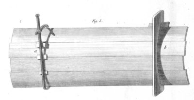
For curved panels [in plane], they hardly differ from straight ones. As to the manner of joining them and gluing them, it is only a matter of using a clamp to bring together the joints because when these same panels are a bit curved, the clamps always make them a bit more or less curved than is necessary. You remedy this by putting cauls between the panel and the clamps [bar], which is always placed at the side of the bulge, as you can see in figure 5, side a. No matter what precautions you take, the cauls that you are required to tighten or loosen twist the joints and prevent the glue from working properly. Even when the panels are thin, the clamps bend them and even break them. That is why it is much better to make cradles that you [cut] hollow in the same shape as the panel, which you join and hold in the cradle by means of a wedge, see figure 5, side b.
There must always be at least two of these cradles for gluing a panel and even three for one a bit larger. One should also observe that the angle of the hook “holding the wedges” of these cradles be a bit sharp [acute] so that the panel cannot shift when closing it, see figure 6.
I do not know how to conceal the fact that this method takes much longer and consequently is more costly than the first one because it is necessary to make as many cradles as one has of panels of different curves. These considerations should diminish the advantages that result from using these cradles. These same cradles also serve to fasten [peg] the curved work, which is always better than the clamps, which distort the joints and sometimes break curved crosspieces.

The second approach, marked “b” in the top drawing and important enough to make another detail drawing to communicate the essence of it, makes more sense to me. In fact I have used this approach countless times beginning back in the pattern shop where we produced dozens/hundreds(?) of core boxes for creating cores for casting pipes. Although our patterns were permanently assembled, the process is conceptually identical to using a coopering cradle.

The general process is pretty fool proof. First, lay out the curve with a compass or trammel on a pair (or more) of wooden timbers. Cut out the concave form. Since these would be used for gluing it is almost certainly true that these would be slathered with wax or tallow to prevent the curved panel from being glued to the form as it is being built.


Saw as many staves as are needed for the panel being built. On the edges of the staves plane or saw a slight chamfer so that the staves fit nicely into the curved form, with intimate gluing surfaces aligning between each stave. This angle can be determined during the layout of the panel, and transferred with a bevel gauge.

Place the beveled staves into the form to confirm the fit. Make sure the forms are square to each other.

Fill any extra space with loose boards, and pinch the curved panel staves together with individual or compound wedges. If there is glue between the coopered staves, once that dries the task is finished and after knocking out the wedges the curved panel can be removed to work further.
Once the convex triple moldings were established effectively to my satisfaction the time came to cut the tiny rebate on the outer edge of the foot. That step took a couple of tools, one a modified marking gauge and the other a very simple rebating scratch stock.
For the marking gauge, which in fact I had set up already as a slitting or cutting gauge with a sharpened knife cutter, I needed to modify the block so that the beam could follow the radius as the contour swept in and/or out along the outside of the element. The intricate technology required for this modification is no doubt intimidating, but it was really nothing more complicated than sawing a 1-inch dowel in half and adhering it in place with double stick tape. I also relieved the shoulders of the gauge block to allow for even tighter turning, which would be needed for the leg moldings.


This allowed me to scribe the inner shoulder of the undulating rebate with little effort.

The follow-up tool was a scratch stock fashioned from a piece of tropical hardwood flooring with a tiny rectangular exposure that scraped out the rebate perfectly. On the first foot I cut the three convex beads first followed by the rebate. After that I reversed the order of the process.

The end result was satisfactory.
Then I broke my right arm and was out of commission for another few months. See what I meant about the client’s patience?
The decorative elements of the desk, in fact the base frame of the piece, were all about deeply incised moldings on the edges of every planar element. I would estimate that the construction phase of the base was about 90% for making the moldings, about 10% for making the joinery.

Once the individual elements were cut and cleaned up, I set to work on making the moldings on their edges. Given the nature of the moldings this was a multi-step process, using some tools that I bought and many more that I made or modified. I began with those surfaces that were the most amenable to trying and perfecting the technique, namely the feet. They were manageable in size and complexity, and completely accessible since I was working them prior to assembly.
In essence these were not carved moldings early as much as they were “scratched” moldings, in essence created with a series of scratch stocks. So, my first step was to fabricate a slew of scratch stock cutters to configure the primary shape of the three half-round runs on the edge of the feet. I ground a center flute cutter from a blank from my inventory from the English profile tool to establish the valleys, and a Lie-Nielsen iron needed only a bit of tuning to work just fine to perfect the convex rounds.
Beginning with Mr. Tefft’s seventh grade drafting class I have been fascinated with pencils and their sharpening. I am by no means an expert or total sharpener history aficionado like Mister Stewart or Chris Schwarz, who can regale each other with tales of pencil sharpener arcana in perpetuity (which I have witnessed) but I am appreciative of the technology, especially when it works properly.
The whole notion that the world of pencils was so much larger than the mundane No.2 we needed to complete standardized testing captivated me. Between my years in junior- and senior-high drafting classes and my subsequent years as an architecture student, back in the day when we still rendered our plans by hand in pencil on K&E tracing paper, my attraction to both high-quality standard and mechanical pencils grew to an outsized portion. And, while I am nearly devoid of artistic talent, I loved art drawing classes because they allowed me to obtain and use an astonishing array of drawing pencils.
This attraction to pencils was cemented as a utilitarian habit during my decades in the museum artifact world, where pens are generally forbidden in proximity to antiquities as they can accidentally leave disfiguring stains but pencils are much less likely to cause permanent damage. For years all of my observations were recorded by pencil in notebooks simply because that was the yardstick for the trade.
Heck, even one of the greatest political tracts of all time was titled I, Pencil.
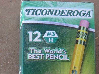
To this day I use a pencil in the shop far more than striking knives or mortise gauges and the like. I even special order No. 3 pencils for laying out joinery, the hardness and sharpness of the lead leaving a crisp line that incises the wood much as does a marking knife. And thanks to my long-time pal MikeM I have a stash of No. 1 pencils and he steered me toward high quality white china marker pencils, perfect for making darker woods. Due to their softness, sharpening them is a delicate task.
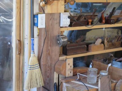
An old-fashioned pencil sharpener is screwed to the timber post immediately adjacent to the door entering my shop. For years I have obtained and tried out numerous pencil sharpeners, as I am pretty fussy about them and I use them several times a day. In all these years I have never encounter a pencil sharpener to compete with The One. The one in Tom’s shop, the pencil sharpener by which all others were judged. Forget “One ring to rule them all.” This was important.
On one of my first Wednesday evenings working in Tom’s shop I needed to sharpen my pencil and asked if he had a sharpener, honestly expecting the answer to be “No.” Instead he led me to a boxy looking thing I think was mounted to the wall. When I inserted the pencil into the device and started turning the handle I swear I could almost hear angels singing the Hallelujah Chorus. I had found The One!
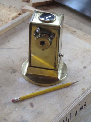
Tom’s sharpener was of Spanish manufacture and operated smoothly with none of the grinding sound so typical to school pencil sharpeners, and left a tapered tip that was flawless. I immediately looked into getting one myself but the scarcity and price scared me off. Tom mentioned that his had been a gift from his mother-in-law and was a bedrock tool for him as he, too, used pencils in his work. For years I have been waiting either for one to come up cheap on ebay.com or for me to talk myself into spending the money on one for my shop. Neither event happened and I just “made do” with my ancient Boston sharpener(s) which usually yielded an excellent tip but occasionally produced one that looked like it had been gnawed on by a beaver.
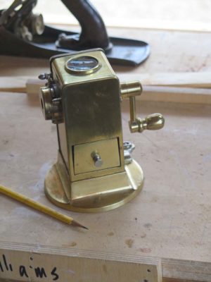
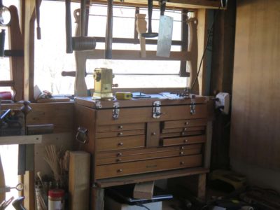
And now Tom was handing me a paper bag and inside that paper bag was a vintage gold-plated El Casco pencil sharpener. I was nearly speechless. Really. It will reside even more prominently than my vintage Boston sharpener on the post, this one will live on the lid of my prized walnut Gerstner tool chest (a Christmas gift from my BIL almost 35 years ago) which sits on top of my FORP Roubo bench.
You just gotta keep friends like that around.

Recent Comments