This is a rare blog without pictures as there is literally nothing to show. It’s almost like Claude Rains telling you to move along because there is nothing to see. But it is not without exciting information (to me, at least).
The return of the hydro turbine core last week was a time of great celebration. I am delighted that I decided to return that unit to the manufacturer for the replacement of the rotor bearings; I did not want to be learning-on-the-job by trying something I had not really done before – replacing the bearings on an expensive, high-stress high-precision delicately balanced machine. I know that come a zombie apocalypse I will have to do it myself or find someone locally who can, so I purchase two extra pairs of the sealed bearings necessary for the task. Given existing performance projections that gives me another 25-30 years of functionality to the unit.
Reassembling the turbine unit took almost no time, 10-15 minutes or so. Reinstalling it into the system took about the same amount of time. Tracking down the location of the breached water line from unrelated storm damage that had occurred since I dismantled the turbine took the longest. A tree branch had fallen and cracked the penstock (the 2″ PVC pipe from the water capture to the turbine) disrupting the water flow to the turbine, and once the damage was found the repair took only a few minutes. I keep a good inventory of repair parts on hand since my water line is above ground, snaking through the forest for almost 1200 feet. I would love to have the water line buried but with our climate, topography and geology it would require digging a three-foot-deep trench a quarter mile in rocky sub-soil. Until I inherit a new family tree with gobs of money I will make do with the status quo.
Once the system was all together and running I knew instantly that something was dramatically different. For starters, the turbine unit was so quiet I turned it over just to make sure it was running! For the previous nine years ever since the system was installed, when the turbine was operating under full load it produced a whine that was distracting for quite a long distance. Since it was that way from Day One I had no idea it was not supposed to be so. But now? Eerily quiet, just barely audible even at the stillness of dusk. Although I know what to listen for I still have to strain a bit from the front porch to hear it working.
A second observation was that the output of the unit had increased a fair bit. I have not yet installed the new digital metering unit for that part of the system, but I can tell the difference in the integral monitor which is nothing more than a blinking light indicating the input current to the charge controller. All I can say is that it was blinking about twice as fast as I had come to expect for that particular water flow.
I wrote back to the fellow who replaced the bearings with these observations, and asked him if he noticed anything during his work (he succeeded the previous owner of the company since I purchased my unit a decade ago). He confirmed that he noticed one of the bearings was not seated properly and he took special care in aligning everything correctly. It appears that the misalignment caused both a whine in the turbine in operation and also some substantial drag on the turbine rotor shaft. Hence the “new” turbine is both quieter and more efficient in operation.
Who knows? Maybe the properly aligned bearings will last 20 years instead of 8-10.
Needless to say I am thrilled with this outcome, and await the developments in the solar panel controller malfunction situation.
Though a minor piece of real estate on the desk, the roundels were certainly visually prominent. Thanks to my four-jaw chuck on the lathe making them was a breeze.
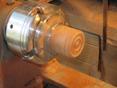
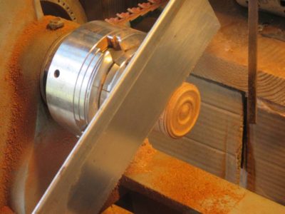
My first step was to make a cylinder from some of the mahogany then turn the roundel profile on the end of the cylinder. Once the profile was satisfactory I scored the lip of the roundel with a turning chisel then sawed off the circular wafer right on the lathe.
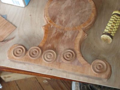
I repeated the process until I had excess roundels, then glued them in place.
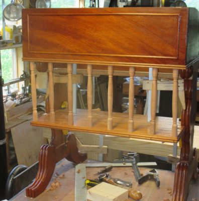
In addition to the roundels there were bits of applied moldings to the field and bottom perimeter of the writing box and along the edges of the shelf. After spending numerous hours making the curved moldings on the legs these seemed like a holiday.
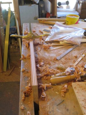
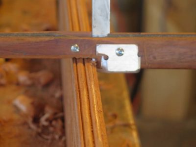
I simply cut the moldings on the edges of a board then ripped them off for application to the surface of the box.


The half-round string moldings in the field of the writing box allowed me to use a set of pinch clamps I’d made years before. These were featured in a Popular Woodworking article some time ago.
The only construction left to accomplish was to complete the top of the desk, then it would be on to the best part — finishing!
Sometimes you get lemon peels, sometimes you get lemon meringue pie.
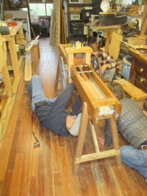
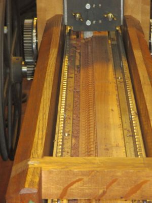
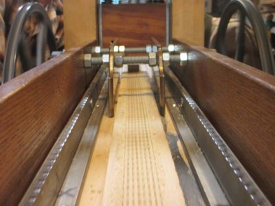
Thanks to a clearing on the calendar we’ll be convening the second Ripple Molding Soiree and Camp Out at The Barn the week of September 3. As before the agenda will be to explore the theoretical and practical aspects of making ripple moldings and their machines.

I think all of last year’s participants are coming, including at least one newly completed ripple molding machine in tow. For this year I know one of the participants is feverishly interested in making a bench top molding cutter to produce diminutive moldings and I am going to work on my prototype from last year and another Felibien-esque c.1675 model vaguely similar to the one we resurrected last year.
As before there will be no tuition fee, this is a mutual learning experience rather than a teaching/classroom event. We’ll share whatever material costs are incurred and pay for our own meals (normally for a workshop I provide or pay for the mid-day meal). If you are interested in participating feel free to drop me a line.
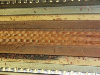
PS if this goes well my pal JohnH and I are hoping to teach a “Make A Ripple Molding Machine” workshop some time in 2019 and also make an instructional video on the same topic.
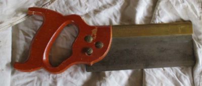

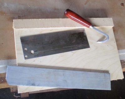
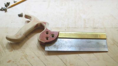
The rehabilitation of my first “brand name” dovetail saw began with dismantling all the components and re-thinking the proportional issues that rendered it an ill-fitted tool for me. As I said before, the cutting edge (teeth) of the saw was about the only thing I liked about it, so that would be left alone but everything else was on the table. Removing the handle was of course no more complicated than removing the saw nuts holding it on. (I’d already mucked around with the handle before I took this picture. Also, note the shallow bedding of the saw plate in the brass back).
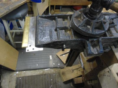

Separating the back and the plate was not much more involved. I set my Emmert vise to the horizontal position and tightened the saw plate in it. With a mallet and a stick I gently drove the back off the plate.
I addressed the easiest part first, the handle. I’ve been working wood for five decades but have not yet figure how to make holes smaller. Given that limitation I was stymied in making the handle and its way oversized hand-opening the right size for my hand, but at least I could make it more comfortable. I accomplished that by transforming it from a closed tote to an open tote, albeit a pretty ugly one. This did allow for and encourage a more comfortable grip on it and is an immense improvement. Still, I will make a whole new handle once I get a little ahead on the multitude of other projects occupying my days.
Next came the re-dimensioning of the saw plate which was just wa-a-ay to tall for my taste. Previously the distance from the teeth to the top of the spine was almost 3-1/2 inches, a pretty excessive proportion for an 8-inch saw. Some of this was due to how the plate was bedded in the back and some on the depth of the plate. The plate was a very hard piece of tool steel, probably cold-rolled sheet that was effectively forged and thus too hard to saw through. It was also too hard for my little sheet metal shear to cut through so I had to use a different approach.
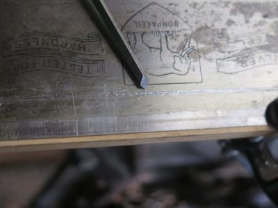
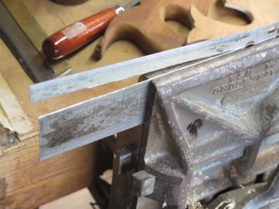
Instead I scored the plate with a scribe along the line I wanted to cut. I then used an engraving burin and took several passes along the scribed line to create a furrow, weakening the plate to the point where I could break off the excess. It worked like a charm.
I finished this slightly jagged edge with a diamond stone and it was ready to go back in action.

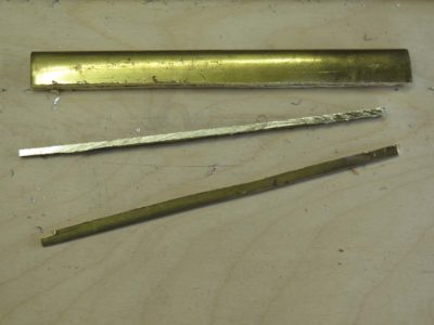
My final major modification was to narrow the brass spine. The saw was originally fitted with a bent back made from 1/8″ brass with a 1-1/8″ depth making it a stout, really heavy component. On a saw this small it threw the balance way off, another feature I did not like. I did not necessarily mind the depth of the back but it was just too massive as it was. Using a hacksaw I ripped a proud quarter inch from its depth, then finished the edge with a file resulting in a brass spine that is almost 1/3 lighter and narrower than it was before.
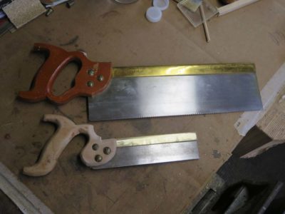
One final modification was to re-set the plate fully bedded into the bent back, as opposed to the original bedding that was only about 1/4″ at the tip of the back. The result of this combined with the cutting-down of the plate resulted in an 8-inch saw that was only about 2-1/4″ in overall depth versus the original 3-1/2″. This improvement alone was worth the effort as it makes the saw feel like more of an extension of my hand rather than some barnacle stuck there.

With all the old pieces made new, the reassembled saw more closely resembles a tool I might use regularly. The relatively heavy set for the teeth, at least when compared to my no-set tapered saw plate model, feels a little “wallow-y” in the kerf but performs well. I can definitely see this old/new saw becoming part of my regular repertoire of options.
Because of the rigidity and (light)weight requirements for the portable restoration workbench, the obvious choice for the top was a torsion box, the construction of which was virtually identical to those described in the woodworking literature. My first attempt used 1/4″ faces and 1/2″ ribs of luan plywood. The weight and rigidity were good, but the working surface of luan was a little too fragile. Nevertheless it was a confirmational “proof of concept” exercise.
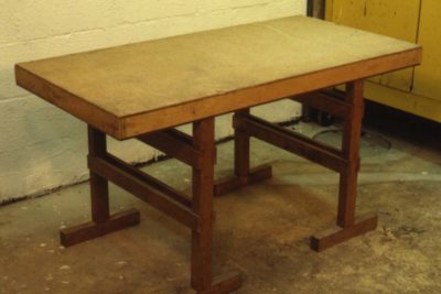
My first step was to make a simple torsion box as a test run. It was near-perfect as the top and working surface. I faced this prototype with cork on one side and plastic laminate on the other, and it remains in use in the shop to this day almost thirty years after being made.
Concept One – check.

My first inclination was to make a trestle base for the bench, but considering my master scheme this idea had some significant drawbacks. While easy to build and assemble, the knock-down/assemble/disassemble trestle requires multiple parts, and one of my stated intentions was to not build anything that required keeping track of lots of pieces. Instead, on my first attempt I tried using a pair of commercially available tubular-steel folding-table legs. These worked fine along the short axis of the bench but weren’t stiff enough along the long axis because of short diagonal braces. Though a good concept, this shortcoming and the unnecessary weight of the steel legs made it a non-starter as a final option. Even with those hefty legs the unit weighed in at only 55 pounds, well within the limit I wanted.
Concept Two – check.
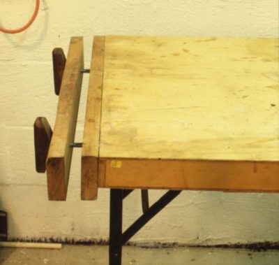
As for the vises I simply used pieces of 2x stock cut to match the dimensions of the ends of the top combined with 3/8″ steel threadstock from the hardware store and some wood handles epoxied onto the ends. Again the concept was successful but the fine-ness of the thread made the vises tedious to use.
Concept Three – check.
Finally I threw on a piece of upholstery webbing to serve as a shoulder strap so the folded bench could be carried and maneuvered easily. That concept was an absolute winner. Throwing the strap over my shoulder it was a breeze to navigate the twisting rabbit trail to a work site.
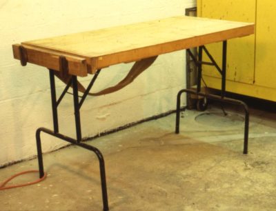
As a final test run I took the prototype to a job and it worked out just fine within the confines of the limitations enumerated above. With what I learned from this it was time to move forward with a final iteration.
Check, check, check, and check.
By the way, this bench is still in use but as a food preparation station for the barbecue.

Like a multitude of fellow craftsmen my interest in traditional woodworking was fostered by the book Make A Chair from a Tree by John D. Alexander, Jr. I probably bought it shortly after it as written, then a few years later I also purchased the excellent companion video. I cannot recall now if that video included some delightful bantering with saw maven Tom Law, or if it was Tom’s video on saw sharpening that featured bantering with John Alexander. Either way it was an engaging and delightful foray into learning. (Actually one of my great curiosities is why the producers never made any more videos; their video with Tod Herrli is simply one of the best instructional videos I have ever seen on any topic.)
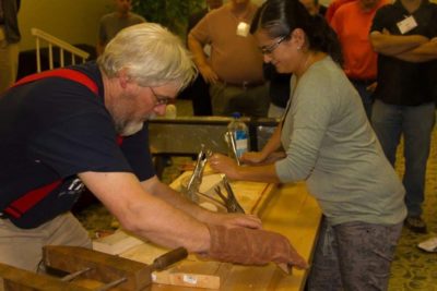
I never really became chair maker, my Gragg chair adventures notwithstanding, but the approach of thinking through then executing a project resonated with me. Mr. Alexander’s blend of historical understanding, winsome wit and practical craft applications served him well as an evangelist for the cause.
The chronicle of his entire journey is recounted here by the inestimable Kara.
I read recently of his death not too terribly far short of 90 years, and reflected on the transforming power of solid scholarship blended with infectious enthusiasm. Our paths never crossed in person, but I offer my condolences to those who knew and loved him.
I am delighted to report that both electricity-producing components for the barn have been repaired and are en route on the return trip. If all goes well I will be reinstalling them later this week.

Yes indeed, soon enough there will, once again, be light!
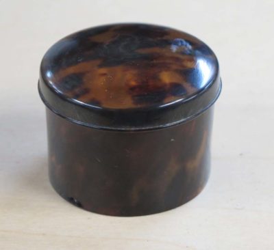
Recently I was puttering around my basement shop in my daughter’s home and came across a lovely little tortoiseshell box. My first response was to wonder where I bought it (I cannot remember, it was very many years ago). My second response was, “Hmm. I wonder where my box of other tortoiseshell boxes and vintage lacquer boxes is? I sorta know the answer to that one is, “Somewhere in the barn. You just haven’t unpacked it yet.”
A third observation leaped at me as soon as I got the little round box out into the light; it was a wleded box, scraped and turned on a lathe, made from a scute (plate) from the carapace (back shell) of a hawksbill sea turtle. What we call tortoiseshell comes from one of two sea turtles, hawksbill and greenback, the different shells being as different in morphology from each other as are the habits and diets of the two turtles.
In terms of its constituent components, if you thought of a piece of tortoiseshell as a fingernail with freckles you would not be far off. The main structural difference is that your fingernail grows in a linear pattern from the bed of the nail, while a tortoiseshell grows as a full layer across its entire area. For reasons that remain unclear to me, even after lengthy discussions with herpetologists, why the nature of the two species’ scutes are so different.
Tortoiseshell from a greenback is usually only 1/32″ or so thick and pretty uniform in that thickness. In other words, they do not build up much thickness. Hawksbill scutes on the other hand can reach more than a quarter inch in thickness at their center, and a part of the craft in tortoiseshell-work was the ability to split and delaminate the hawksbill shells for greater yield.
And, since hawksbill shells are comprised of an ever-increasing number of layers, when that shell is worked and mechanically thinned with scrapers or abrasives the layers are not penetrated with perfect evenness. The result is a pattern that is often called “watermark” in other contexts, paper and silk for example. Sometimes the pattern is difficult to discern, I have tried many times to show this to conservation students with varying levels of success. It really is trying to find a pattern of shadows lurking deep in the mass of the shell.
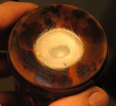
Fortunately for this post my little round box’s watermark pattern was impossible not to see on the outside of the top.

The inside of the bottom was a bit trickier, but the watermark pattern is there too.
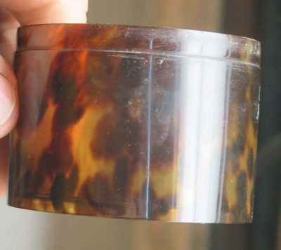
On the outside of the welded and turned the watermark was just a shadow hiding just below the surface.
Now you know.
This is the next of an occasional series on the workbenches I’ve built over the years. — DCW
=======================================================
By the late 80s not only was my young career at the Smithsonian humming along but my outside work for private clients was keeping me as busy as I wanted to be. An awful lot of those projects were “on site.” Whether the client was a private collector or an institution, with increasing frequency I was working at their location. There are many reasons for this; cramped quarters at home, the legal liability of transporting very valuable objects, the cost of renting a truck and hiring someone to help out (I usually work alone), etc. Regardless of the cause I often found myself working in unfamiliar, and usually unequipped, surroundings.
Thus, several times a year I would move lock, stock and “workbench” (saw horses and plywood or door) to a new location, a truly onerous activity. One project in particular, in a museum’s sub-basement down three flights of a spiral staircase, provoked me to build a high-performance lightweight folding workbench that remained in use for many years before retiring to the deck o serve as a serving table when I cut back on my on-site work. I have improved on both the design and execution of the bench in recent years but for now I will stick to the 1989 prototype and the 1990 finished bench.
This growing commitment to on-site work justified a little investment of my time to work out the problems inherent in occupying space that was not my own. In the end, that process of finding a “better way” resulted in the design and fabrication of a new workbench and some companion accessories to make the task of working in a portable studio more manageable and productive.
What did I want?
The only thing I was sure of was that my sawhorse and plywood routine had to go. But what arrangement was to take its place? Being a lazy fellow, my first actions were to look around at the market to see if any of the available “portable” workbenches were suitable.
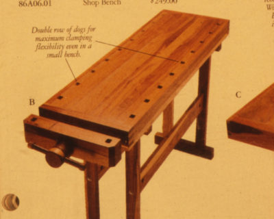

I discovered only two real options; a small, pseudo knock-down version of the European-style butcher-block-top bench, or a Workmate. I looked at a couple of the former, and own one of the latter. I found the portable Eurobenches to be too small and unsteady for my use (and quite frankly, too “cheezy”). In addition, they still weighed-in at around 100 lbs. Since I would have to carry it by myself, it was simply too heavy. I tried my Workmate on a couple of projects, but it wasn’t exactly what I really wanted because it was too top-heavy and the work surface was too small. My search for a manufactured bench to suit my needs wasn’t exhaustive, but nevertheless, I decided to design and build my own portable workbench.
The process of procuring a new, high performance portable workbench began with the question of exactly what I wanted out of the bench, regardless of its source. When I decided to make my own, I had only to review those requirements and build to fit them. Back to the original question, what were my specifications for the bench? The answer was simple; 1) the top had to be perfectly flat and about 2’x 4′ (any smaller and I might as well stick to my Workmate, much larger and it would have been unwieldy for some of the pathways I had to traverse), 2) it had to have a vise sturdy enough to take a modest beating, 3) the bench had to be very light, compact, and easy to set up and take down because I didn’t want to have to assemble a kit each time I moved, and 4) it couldn’t cost a fortune in time or money to acquire. It was also important to remember that the bench wouldn’t have to stand up to immense weight or stress, since the pounding necessary during general joinery was rarely required in a conservation project. Any particularly heavy work dictated by a specific treatment would still have to be done at home.
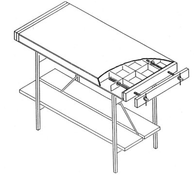
The bench I ended up with was not an example of exquisite handworked joinery, but it did require precise machine woodworking techniques. The bench shown here is my second version and still not perfect, but it is completely functional and does satisfy the requirements listed above. It might be bragging but I think it remains the finest high performance portable bench design I have encountered to date.
The top is the right size for my needs at the time (although it could be made any size), and contains a pair of 24″ twin-screw face vises at the ends which opened about 12″. The bench folds up into a compact unit weighing only about 50 lbs., making it extremely easy to move about. In fact, the lightness presented another problem which I will describe later on. The long diagonal braces, which fold with the legs, provide plenty of stability to the bench allowing even more aggressive cutting and pounding than I had hoped for. In addition, I built several accessories which enhanced my capabilities for restoration on-site. Finally, in terms of both fabrication time and materials cost, the bench was very inexpensive. It took about six well-planned hours and $75.00 worth of materials to build, plus about $25 of machine-shop time (in 1990 dollars). You can fancy it up as much as you want, but you can have the basic unit quickly and inexpensively.
Next time — the “proof of concept” prototype
Forty years ago, being younger and foolisher, I believed that buying “Name Band” pricey hands tools was necessary for good craftsmanship. Turns out that might be true sometimes, but not always. In fact some “name” brands are capable of producing dreadful products, poorly designed, poorly executed, and actually moving you backwards as a craftsman. Or, sometimes it is just that your way of working is not reflected in the way the tool works. Such is the case with my first “professional” dovetail saw.
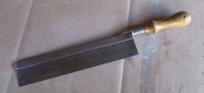
Prior to that moment I had been “making do” with this un-branded “gent’s saw,” progressing in my skill to the point where I was making real dovetail-ish constructs. Given my circumstances at the time I am nearly 100% certain that I bought this saw at Sears in the mid- to late ’70s, back when they were a purveyor of quality merchandise rather than a real estate management/liquidation enterprise. But as I fell under the thrall of the Fine Woodworking ethos it became (falsely) apparent that I needed better, brand name, tools to make better progress.
Then came a third try at college with the three years of a highly restricted purchasing and time regimen attendant to that. In 1984 I started employment at the Smithsonian Institution’s Conservation Analytical Laboratory, allowing for a modest tool budget. This was in the days prior to our current Golden Age of Tools and tool making so the options available to anyone outside the vintage tool network were limited to one or two mail-order catalogs. So I went to the best hardware and tool store in the DC area and bought the best, most “Name Brand-y” pair of back saws they had. How was I to know in advance that the “dovetail” saw was dreadful? It only took me one or two sessions at the bench to realize that this was the case.

Everything about this saw’s ergonomics was wrong. The handle did not fit my hand as nicely under fire as it did when being admired at the store (was Angus MacAskill their hand model?). And though the cutting length was nice, in fact the teeth were excellent, the height of the saw plate combined with the absurd weight of the overly stout brass back made the thing so unwieldy for me that my facility at cutting joinery actually regressed when using it. It might have been a fine tool, in a purely theoretical sense, but it was not suited to me.
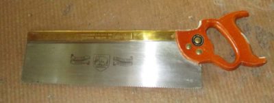
The odd(?) thing is that the companion tenon saw I bought, same time, same maker, suits me almost perfectly for its purpose.
So I tossed the dovetail saw aside for more than two decades, no, make that three decades. With my little gent’s saw I made steady progress in my workmanship. I even augmented that with a Bad Axe standard issue dovetail saw early in that company’s existence. Though these were excellent saws I found that when working in thin stock making petite joinery they were too aggressive.
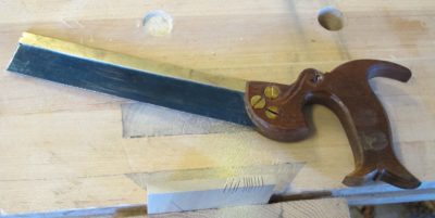
Me being me, I decided to try to make my own little saw and that outcome was excellent, resulting in not only a perfectly suited saw but even better, some Ivory Tower Coin of the Realm — a publication! I continued making more saws, becoming more confident in them, giving most of them away as I finished. I even commissioned Bad Axe to make me a custom saw based on what I learned in making them myself, and that saw remains an integral part of the inventory.
But let’s return to the saw whose shortcomings led me down this path; could it possibly be rehabilitated? After all, the cutting edge was excellent, it was just everything else that was not.
Next time — the rehabilitation.


Recent Comments