It’s been quite a while since I 1) did any Boullework and 2) made a public presentation.

The last week or two I’ve been going through the exercises I’m demonstrating this coming Saturday to the SAPFM Blue Ridge Chapter, everything from making tordonshell to cutting some new Boullework panels.

When I assembled the metal and tordonshell packet and set about to sawing, the magic just wasn’t there. On a normal day once I get in the rhythm I can go for an hour or longer per saw bade, sometimes even half a day. But not this particular day. Sigh.

I was snapping blades like I was trying to break pasta. It took me four hours to saw a 1/2″ circle (and a pretty raggedy one at that) and I broke more than two dozen blades in the process. When I swept up the pile was truly impressive, but my camera was not handy.

Bad posture? Bad lot of blades? (it really does happen some time) Packet too thick? Rusty antiquated shoulder? Vision problems? (well, that is a given)
Some days are just like that. I’ll aim to get the bear tomorrow.
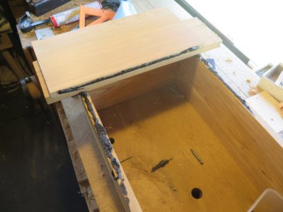
With the dovetailed box sides assembled I moved on to attaching the board bottom. The orientation of the wood there was such that it will cause the maximum swelling and thus compression sealing that panel.

My strategery was to lay down a bead of asphalt and screw thing down tight for each board. I left each board over-length by about an inch to reduce the risk of splitting from the screws. I left the end board even longer to allow for a more stable outrigger effect when sitting in the stream after installation.
The successive board was tarred to both the sides and the preceding board. Tidiness was not the objective, sturdy durability and performance was. My only real objective was squeeze-out.
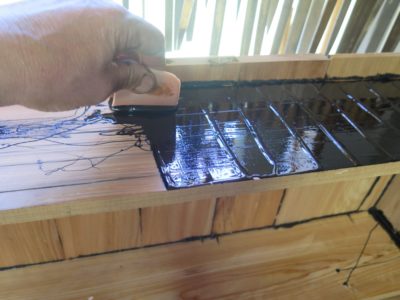
When the bottom was in place I turned my attention to one of the side boards that had a bit of surface cracking. I trowelled on some tar on that whole surface just to make sure it would remain intact. Probably overkill.


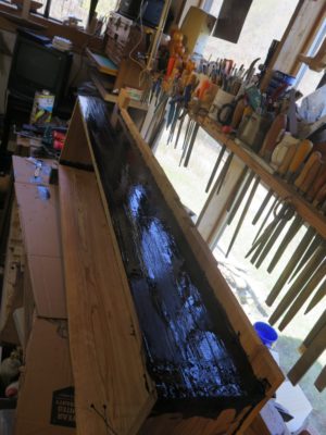
A line of tar on the inside and outside of each corner completed the assembly. Using a hole drill I installed the shower drain fixture that served as the connector for the penstock water line.
Now all I had to do was make the screen lid and haul the monster up the hill.
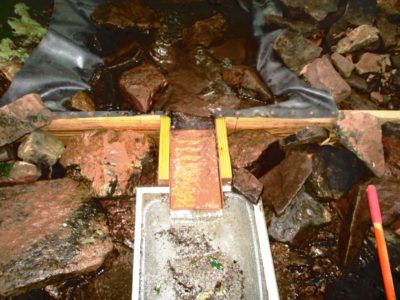
Not only was the severity of the winter weather manifest in the damage to the pipeline and master valve, the existing intake setup (pictured above) at the top of the system was thrashed. The Rubbermaid tub was several yards downstream from the weir (dam) and the copper chute was missing altogether. I cobbled the system back together to give myself a few days to make a new capturing basin. The time had come to construct the collector box I have vowed to make ever since installing the system.
Using some of my prized c.1840 11/4 bald cypress lumber I made the box I have always wanted. The first step was resawing the 11/4 stock into three equal boards roughly 4-feet long and eight inches wide for the long sides and a foot long for the ends, and the requisite number of cross-boards for the bottom. I started the process by cutting the initial kerfs on the table saw, then finishing the task by hand (the lumber was too wide for my upstairs band saw. I could’ve used the resaw bandsaw in the basement but would have had to move a whole lot of stuff to excavate it.) Sorry, no pics for this process.
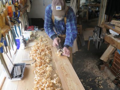


The boards were foreplaned as the finished surface. Incidentally, even though the wood is 180+ years old it is still tacky on the inside when re-sawn and planed, and cypress’ typical smell of patchouli oil fills the air! BTW I hate square-post-through-the-bench-top planing stops a la Roubo and always have. I much prefer the right-angle stop in the leg vise as shown here. It’s just how I roll, or rile, or whatever.

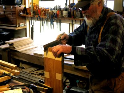
With the lumber prepped I set to cutting the dovetails in the corners. As is my custom I cut the tails on both pieces at the same time. Normally I nail the two boards together but this time I decided to tape them.


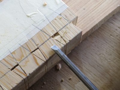

Another of my multitude of peculiarities is a dislike of sawing out the dovetail waste. I just incise the shoulder, pare out a bit, then go back and wail on the waste. In a minute or two they are done. I cut the pins basically the same way.
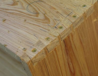
The dovetailed corners were screwed together with decking crews (pre-drilled and countersunk) since adhesive was not likely to perform permanently under water. With the screws and the swelling from the moisture I expect these joints to remain tight until forever. Even so, before installation I slathered the corners inside and out with tar, just to make sure.
Stay tuned
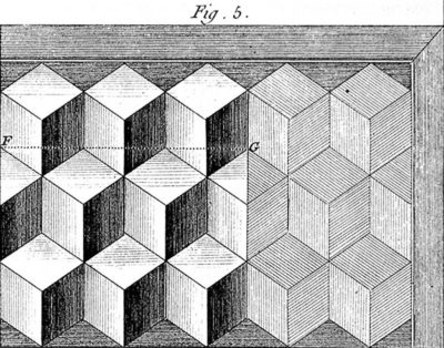
When discussing the layout of parquetry patterns, Roubo is adamant that the primary pattern must be either whole or half units of the geometric composition, that having a partial sequence of random width was low rent. With that in mind I began to layout the parquetry pattern I wanted for the shell of the tool cabinet.
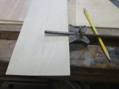
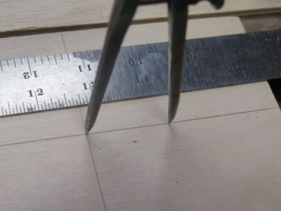
Using the literal dimensions of the cabinet width I began the process by shooting some guide lines then stepping off the fragments of the design using my 30-60-90 triangle and a set of dividers.
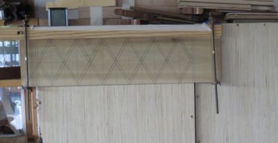
A la Roubo, my exact measurement was unimportant. What was important was that a primary east-west composition turned out to be exactly X number of full units wide, with the adjacent rows above and below that main row would comprise of X-1 units terminated with two half units.

Once this was accomplished I was able to lay out the sub-units of the of each parallelogram in the Roentgenesque fashion I was shooting for.
Now it was time to begin sawing the requisite veneers from the blocks of Roubo-era oak scraps, and from them to create the diamond patterns to see if the composition worked as well in reality as it was looking inside my imagination.
Stay tuned.

I am delighted that in the aftermath of being disinvited from the Winterthur conference on marquetry, the Blue Ridge Chapter of SAPFM immediately extended the invitation for me to make my presentation to their group on May 21 in Fredericksburg VA, at Woodworkers Workshop, 1104 Summit Street. I will be the afternoon speaker/demonstrator. It’s my first traveling presentation in more than two years and I am looking forward to it.
You can get any particular information you need through the SAPFM.org website if you are interested in attending, or you can let me know and I will forward your interest to our Chapter Coordinator. I think there is a $10 fee to cover coffee and lunch.
In related news, I will be one of the presenters (Historic Finishing) at the SAPFM Mid-Year Conference, coincidentally also in Fredericksburg, June 26.
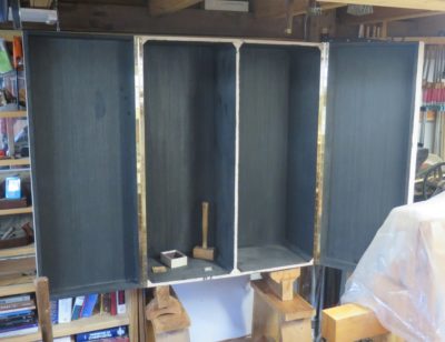
With the box and doors constructed the slow task of arranging the interior of the tool cabinet interior will unfold over the next several months. I have at best a vague master plan other than to “compose” the interior space slowly and deliberately, with no doubt a detour or eight along the way.
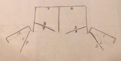
My overall scheme reflects the capacity. The drawing above demonstrates the plan of the tool cabinet with its four interior hinged panels, yielding 12 panels on which to mount tools. In addition, there will be eight drawers at the bottom of the case interior, four on each side.
At the moment my organizational strategy is as follows:
Panel 1 – carving chisels
Panel 2 – spokeshaves and other carving/shaping tools
Panel 3 – bench chisels and joinery mallets
Panel 4 – layout/measuring tools
Panel 5 – smaller planes
Panel 6 – larger planes
Panel 7 – larger saws
Panel 8 – smaller saws
Panel 9 – layout/measuring tools
Panel 10 – files and rasps
Panel 11 & 12 – don’t know yet
Check back in a year and we’ll see how close I stick with this plan.
In total, Panels 1, 2, 3, 6, 7, 10, 11 &12 combine to provide 48 square feet of hanging tool storage, and Panels 4, 5, 8 & 9 add up to another 18 square feet. We’ll see how much I can stuff in there.
In case you were wondering, and even if you were not, many of the tool fittings will be screwed from the outside of the case. Hence, I think the decorative parquetry is still a ways down the road even though I have already begun designing that as well.
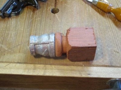
With one end of the head now embedded with the turned padauk plug I fired up the lead smelting cup. To make sure the opposite end of the head was plugged I clamped a scrap of plywood over the end with several layers of aluminum foil as a gasket, and poured in the molten lead.

Since the lead shrank on cooling I had to dribble on a bit more of the molten material to fill the void to a slight excess.
I filed the face of the mallet flush with the margins of the plumbing fitting, then epoxied on some 3/16″ cowhide.
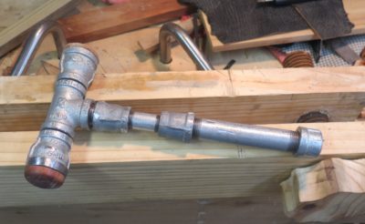
Trimming that flush with the edges of the face let me move on to the final assembly of all the plumbing parts.
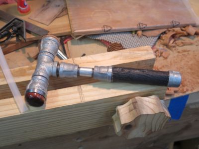
After saturating the padauk plug with dilute epoxy, the final step was to apply a couple layers of sharkskin to the handle. Just because.
In the end, it was a fun project but I am not persuaded of its efficacy due to the ungainliness of the head; it seems too long to me. I’ll probably make another one with a fatter and shorter head.
Stay tuned.
the had now filled with cast lead it was time to finish the assembly and wrap it up.
Once I got the water flowing through the repaired penstock I trudged down to the turbine to check the result. As I approached the turbine I was gratified to hear the soft whine of the mechanism, and exasperated by the sound of spraying water. Once I got close enough to see, I noticed an absolute geyser of water spouting from the master valve that allows me to shut down the system to allow for maintenance (read: extracting fogs or crawdads from the nozzles).

So I hiked back up to the first soft joint — there are a half-dozen joints that are actually radiator hose from a bulldozer, held in place by four hose clamps (this method is designed to allow the penstock to blow itself apart without damage if there is an obstruction downstream) and disconnected it. Yup, the master gate valve housing was split, big time. There was no way to do anything except replace and re-plumb the business end of the system. A hairline fracture I could possible deal with. An eighth of an inch? Not so much.

I decided it was time to make some substantial changes to the water routing at the bottom. as it happens I was in town, i.e. “over the mountain” on other business so I dropped into the farm supply store there to upgrade my valve system to a 2″ solid brass spigot valve rather than the low-tech, low cost, and low strength PVC sliding gate valve.

I also decided to take advantage of the opportunity of the completely disassembled plumbing to enact a longstanding goal of upgrading the system and complete the second line into the turbine housing, something I had been hesitant to do while the overall system was working well. This upgrade 1) balances the forces on the impellor shaft by directing the water jet to strike the impeller from both sides, and 2) allows for a near-doubling of the wattage output as well.
For the connections between the new brass valve and the turbine housing I used new 1-1/8″ heater hose from the auto parts store. The water pressure at the bottom of the system is 40-45 p.s.i so these flexible hoses should work just fine.
Finally, the new setup has me contemplating changing my strategy of mothballing the system over the winter. Given the increased robustness of the new valve and the elasticity of the hose connections, why not just let the system run all winter long? Water can flow well below freezing temperatures, particularly water within a pressurized construct (pipeline). This feature is enhanced by particulates suspended in the water itself (the water coming though the pipe is very hard, essentially mineral water) so that fact alone would suppress the freezing point. Thank you Mr. Auletta, my 9th grade Physical Science instructor, for 53 years ago relating the anecdote of the coal fields’ slurry pipelines that can keep on flowing until 15 degrees below zero Fahrenheit, or 47 degrees below freeing! And, if I wrapped the bottom plumbing with heat tape to keep the smaller lines and the nozzles above freezing, couldn’t it keep running all winter long when our coldest temps are just barely below zero, and only for a few hours at a time?
Hmmm.
Time to turn my attentions to the intake end of the system.
One of the key features of The Ultimate Portable Workbench is its weight, or more precisely, its lack of weight and its rigid stability. That is to be expected for a portable bench, designed for on-site furniture restoration projects. This concept has been unfolding in my brain and shop for three decades.
My estimate for Version 4.0 is a fighting weight of 50-60 pounds, not featherweight but manageable especially since it folds flat-ish. Even though I no longer have any plans for on-site work (there could always be a project that temps me, but it has been a very long time since I did any on-site work) I am going to finish this version as a gift to my son-in-law, given his nomadic status (military) for another ten years.
One of the critical improvements in this version is the increase of work-holding capacity to the point where the bench could suffice for almost any woodworking venture. In addition to the two twin-screw Moxon-style vises I figured out a way to incorporate holdfasts into the design and function. The critical thing was, as I alluded before, thinking beyond the realm of steel/iron holdfasts. They work perfectly in this or any other application but they add unnecessary weight. But, what about holdfasts made from lighter material? At one point I thought about trying to cast some aluminum holdfasts myself, but I have had such success with wooden holdfasts I have decided to pursue that avenue enthusiastically.

Following Mike Siemsen’s perhaps tongue-in-cheek reference in his brilliant video I made a first proof-of-concept model. Imperfect to be sure, but successful enough to propel my further development.
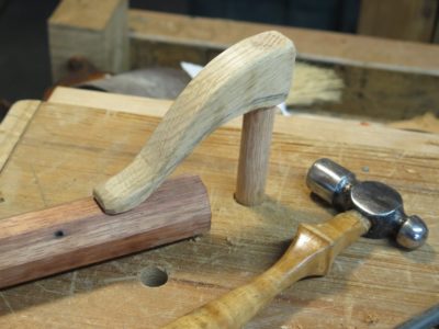
One of the main faults for the initial prototype was that I had not oriented the grain direction of the clamping arm properly. So after a short time in service the arm broke exactly where you would expect. Solving that problem was simple and straightforward, my favorite kind of solution.
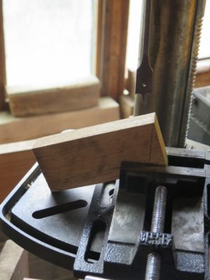
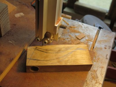
First, rather than making the arm from a scrap piece of pine in the kindling box I used one of the dozens of white oak sample blocks I had boxed under one of the benches. I created these for a corporate presentation many years ago that I would thought was going to lead to a consulting gig, but it never did. I provided a complete set of samples for each attendee in my presentation so I had a lot of these blocks awaiting a new purpose.
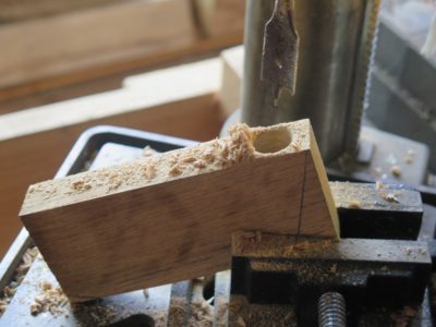
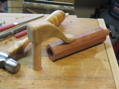
Once I determined the general nature and shape of the holdfast overall I placed the block in the drill press at the inclination I desired and drilled a 3/4″ hole to accommodate the 3/4″ oak vertical post.
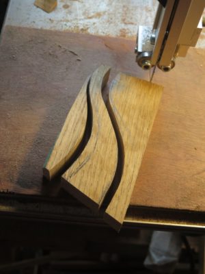

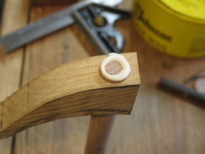
I rough-shaped the block with the bandsaw and glued a length of 3/4″ oak dowel into the arm.
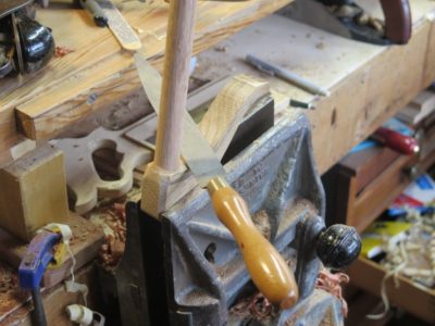
Once the glue was set — I used T3 since I have a lot of it on hand at the moment — I finished shaping the head/arm with rasps.
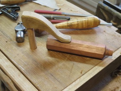
And with that it was done and ready to get to work. I’d guess my total time of fabrication for the holdfast was about 10-15 minutes.
It works exceedingly well, holding whatever piece might be reasonably worked on The Ultimate Portable Workbench.
A while ago I commented on the mallet that Bob Rozieski was using in chopping some joinery (later identified by several readers as a Lee Valley tool), I mused about making something similar myself. I tend to enjoy making tools myself, sometimes even more than using said tools, so making a steampunk mallet could be a blast. In addition, my location in the hinterlands, where the local feed/seed coop/hardware store has both limited inventory and limited hours (and our one local auto parts store is closed on Saturday!), as a result I keep a solid inventory of hardware on hand. Thus the odds were pretty good that I had everything I need on-hand to construct the tool.
Could I turn a pile of pipe fittings and scrap wood into a usable mallet?
Let’s see.
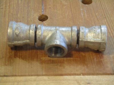
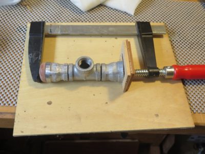
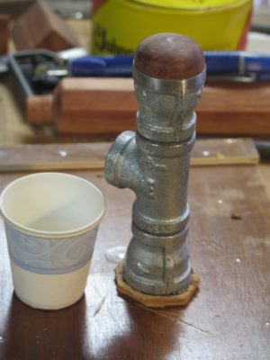
In browsing through my inventory it was clear that I had most of the parts in-hand and needed only to buy a couple of double-nipple 1/2″ NTP fittings and one reducer. I assembled the head fittings together as tightly as possible using my big pipe wrench and a piece of long pipe to act as the handle extension.
So far, so good. Now I just had to figure out how to add some heft. How could I do that? Oh wait, I have several hundred pounds of lead under the gunsmithing bench. And a lead melter; I could fill the head with molten lead. But first I had to plug the ends.

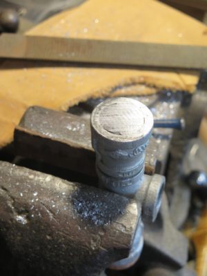
I had already decided to make the mallet to have one end-grain wood face and one leather faced surface. I might as well go ahead and make the wooden face now to use it as the plug for one of the ends. I found a square scrap of padauk in the scrap box and tossed it onto the lathe to turn one end to the taper needed to screw it into one end.
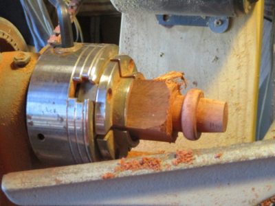
Once that was accomplished i could turn the actual face of the block and drive (screw) it in.
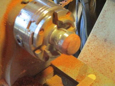
Viola’, I was halfway home.

Recent Comments