Forty years ago I was an aspiring architecture student, and that combined with my years in preserving artistic and historic resulted in life-long interest in design. On the occasional evenings when I am too tired to read or write I might veg out on construction, design or “tiny house” videos on youtube. Although many of the latter strike me as attempts to extend or recapture a pre-adolescent lifestyle by the owners who appear to have few possessions (no room), kids (ditto), or jobs requiring their physical presence or labor, a great many of the projects reveal astounding innovation in space management or construction/design, a vocabulary I keep in mind for our small home.
If I remember my Ayn Rand novels correctly this challenge led her heroic architect Howard Roark to accept the surreptitious task of designing the Courtland Towers although a rival architect was getting all the credit. All Roark wanted was to solve the problem of high density housing that was well designed and well constructed, inexpensively.
I could not help but think of that when I came across this video. I think this solution to a similar problem is ingenious and I would love to see it in person. It highlights the creative responses to the matter of ultra-high density living in New York City, a/k/a Dante’s Seventh Circle of Hell. As much as I admire this design I prefer living someplace where I am so remote I am barely aware of my nearest neighbor.
I was mighty pleased with myself when the bench was finished. It was easy to move, easy to set up and take down, good and sturdy with great clamping. Clearly, I had solved all the problems which led me down this path in the first place. However, a little use of the bench showed me that reality was slightly less idyllic.
Unfortunately, its lightness (55 pounds) which was such an asset in my master plan for the “perfect portable bench” was also a big liability once the bench ceased being mobile and was set up as a work station. The bench was so light I couldn’t really work it hard without moving it or even knocking it over. I had to figure out some way of weighting the bench while in use. My “no loose parts” vision was about to bite the dust.
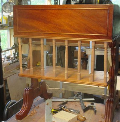
Fortunately, the solution was as simple as building two thin (approx. 1 1/8″) torsion boxes to serve as shelves resting on the crossbar of the end/leg units on either side of the folding bracket, and which could be attached to the underside of the benchtop when not in use. By putting all my tools and supplies on the shelves, the bench now had enough mass for my use. It still wasn’t heavy enough for general cabinetmaking, but it was more than adequate for restoration.
Then a second problem cropped up. The working height for flat-ish or small objects was great, but setting chairs or case pieces on the bench raised them too high. For these taller pieces I needed a lower work surface which would still fit my ideal of lightness and strength. I could have built a lower version of the bench, but instead tried something different. This time I fabricated a torsion box about the same size as the bench top which would fit on a pair of small, low trestle horses. These trestle horses were made from lighter than normal elements, for example the main components were 1″x 1″ and the crosspieces 3/8″ thick.
Some minor modifications to generally employed designs yielded another light, strong and stable unit. By making the top bar of the horses removable, each post of the trestle could then become a tenon. Constructing the torsion box in such a manner that the bottom side had openings to function as extensions to the mortises already incorporated into the grid fitting the tenons of the sawhorse posts, the pieces fit together as a small worktable suited perfectly for holding taller pieces at a more comfortable height. While this new unit was not as “neat” as the workbench, it solved the problem. It also provided more flexibility than simply building another, lower table/bench.
This saga does not end here as I continued working on newer iterations of the concept, but those episodes will be recounted in future Workbench Wednesdays in a few months.
Next week – A derelict salvaged from the trash heap that was transformed into a little jewel.
Except for two specific items that deserve their own posts, my acquisitions at this year’s MJD auction were sparse. I bid on the occasional items but only if it seemed a particularly good and opportune acquisition for a deep discount price, and dropped out of the bidding early once the prices approached fair. I did get a very few things that were cheap and intriguing.
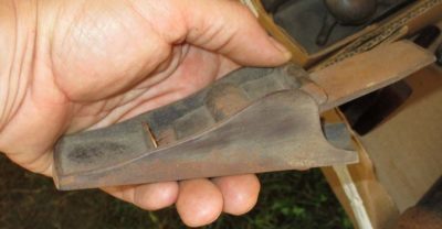
My first purchase was a lot of ebony pieces including a smoothing plane and several navigation parallels. The plane is complete and in pretty good shape, I will brink it up to snuff soon. The parallels will be re-purposed for applications yet to be determined.
A second plane was this odd and huge solid rosewood Japanese plane. Admittedly this was simply a whim, the price was so low I could not pass it up. It weighs a ton, it will be like using a concrete block with a sharp iron. The current iron is pretty much no-account so I will cast around for another.
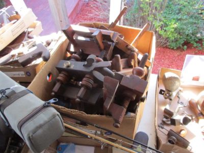
The final small auction purchase was this unusual pair of a sash and cope pair. Unspectacular, but again cheap.
With the light shining at the end of the tunnel, in hopes that it was not an oncoming train there were but a few more elements to fashion and fit and the desk construction would be complete. Sort of. In fact the final assembly did not take place until after the individual pieces were finished, but more about that later. This final construction phase would perhaps be better named the final fitting phase. This included the two top sections, one the writing surface and the other the horizontal back piece all cut from the same mahogany slab, and a little extra enhancement. The back (horizontal) piece of the top was thinner than the writing surface by 1/4″ in keeping with the original.
The “construction” of the top pieces was ordinary to the point of mundane. They only had to be cut to the right size for the places, planed and scraped with a rounded edge planed onto them, then fitted together in a butt joint.
Before the top was glued onto the sides with glue blocks it was the proper time to make the drawer stop. I used a preposterously simple technique I have seen in many small-ish pieces of early 19th Century styled furniture like this replica. A simple flat head wood screw served the purpose perfectly, with the additional benefit that as the dimensions of the case or drawer changed over time to to moisture cycles and any resultant compression set, the depth stop could be easily adjusted infinitely.
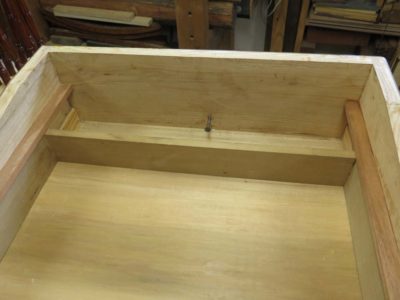
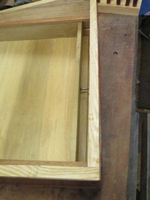
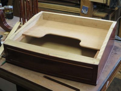
On final little whimsy was to add a hidden “whisky shelf” immediately above the drawer. Since the top was slanted and fixed there was a fairly spacious void above the drawer, and it was not uncommon for a small shelf to be included inside to that a flask of libations could be kept there. I made a “U” shaped shelf that could be accessed when the drawer was pulled part-way out, then tacked the shelf on to the fixed drawer guide rails with a spot of hot animal hide glue.
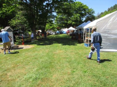
Recently Mrs. Barn and I headed to central New York for the annual overdose of antique tools at Martin Donnelly’s compound in Avoca. It is a phenomenal experience that I can commend heartily to anyone interested in pawing through nearly 100,000 tools, all for sale. The really great thing about this auction is it is the “cleaning out the warehouse” sale of items left over from MJD’s other auction the preceding year. The earlier auctions have a much higher portion of “collectible” tools, this one is mostly “user” tools with little collectible value. Not all, but mostly.
Previewing the auction lots is a nearly impossible task unless you take the full week beforehand; we arrived there the morning of the auction that was beginning at 2PM. I was able to get about five hours of looking prior to the opening gavel.
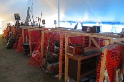
I began with the first 600 lots, which were the opening day’s salvo. Most of these are located in the first of the dozen or so tents on the grounds (there is logic to this arrangement, and the 2nd evening barbecue is in this space so it gets cleaned out first. Most of the box lots for the sale include groupings of tools, sometimes up to a couple hundred small tools. It is a fairly rare lot that inlcudes only one tool, I would estimate that at about 5%.
In the first-day tent I found a few things that interested me, including this solid ebony smoothing plane. It was part of a small lot with several ebony navigating tools included.
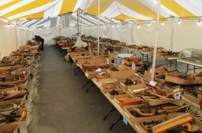
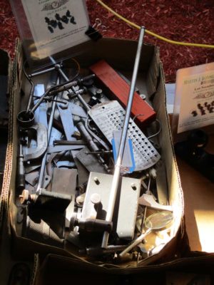
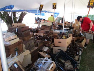
More common were lots like these which included anywhere from a couple dozen items to a couple hundred.
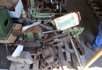
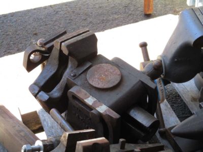
About 1-in-25 lots is oversized and thus in one of the several tents full of bins or palates. After browsing through the box lots in tent #1 for a couple hours I wandered through these tents and found some real treasures to be sold later, especially on Day #2. One palate of heavy iron included THE tool I went to bid on, an Emmert Universal Metalworking Vise. I’d been on the hunt for one of these behemoths for many years, always losing out when the bidding entered the stratosphere. Maybe this was the year.
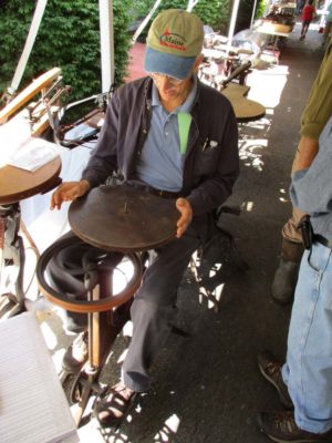
There was stuff everywhere, including the largest selection of foot-powered machinery I had ever seen in one place. There must have been about 50 of these machines, including the pedal-powered shaper my pal MikeM is trying out.
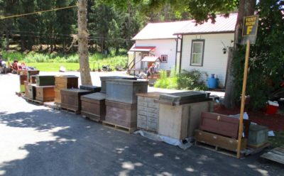
There was even an avenue of tool chests out along the driveway.
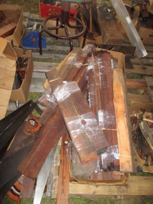
Another tent for oversized lots included this pile of several hundred pounds of Brazilian rosewood, cocobolo, Gaboon ebony, and even more. It came from an old closed yacht manufacturer in Long Island.
Still more giant tents stuffed to the gills with tools, baskets, boxes, you name it. This included a fair number of boxes I was interested, at the right price of course.
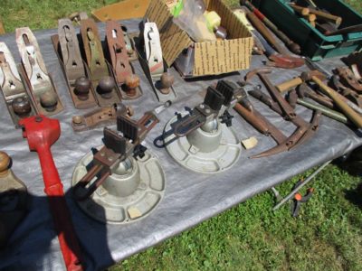
And this does not include the two-dozen small tents and tailgates of tool swapping out near one of the parking areas. I have learned to have a lot of fun with the wheeling and dealing here and can often learn a lot of tool lore with the dealers.
This fellow had two older Panavises that my pal JohnH and I were interested in. His wallet was the size of a hoagie roll. One friend of mine who was selling here confessed that she used to make fun of old guys with big wads of cash in their pockets, the had to confess further that she had become one of them.
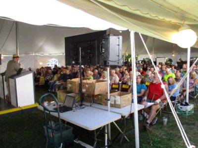
Soon the time raced to the point where folks filled the bidding tent, and the contest was ready to begin. Martin Donnelly greeted the crowd then turned the show over to the auctioneers, whose goal is to gavel four or five lots per minute until all 3000+ are gone. You snooze, you lose.
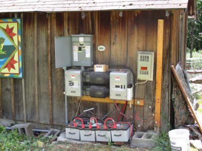
With all the disruption of two robust independent electricity producing systems going belly-up at the same time I decided to add another producer into the mix, is essence to modify the “two is one and one is none” rubric for logistical planners into “three is two, two is one, and one is none.” In the absence of the hydro and solar electron hamsters I relied on my gas powered generators and a bunch of extension cords.
I decided to contact the local electrician to see if he could wire the generator into the service panel of the barn, and he suggested instead wiring it into the power system at the bottom of the hill, alongside the electrons provided by the hydro and solar units. I got a quote, smacked my forehead and said, “Of course!”, and authorized the work. Plus, since there was already a buried cable from the powerhouse to the cabin, could he perhaps also wire that into the system? Sure, he sez.
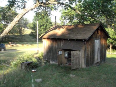
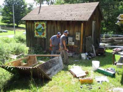
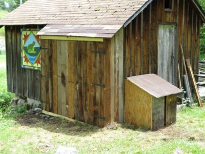
The day came when he and his son, also an electrician, arrived to do the work. The first step was to clear the work area, which translates into “ripping off the raggedy shelter over the electronics closet.” I’d been wanting to do this anyhow in order to build a more proper enclosure for all these components so this was the time.
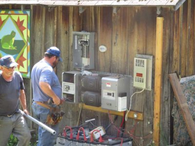
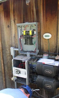
In no time flat they were abuzz with work, installing a new sub-service panel to provide for vastly improved current distribution.
After a bit of time they separated so one was completing the sub-service box to serve as a new router for the electricity and the other was making the modifications to the service panel inside the cabin, alowing it to be powered by the same auxiliary system.
By lunchtime they were finished and I test drove the system in all its iterations available at the time: inverter/battery bank power to the house or barn, gas generator power to the house or barn.
Brilliant!
I spent a couple days making more proper housings for the system electronics and the generator and this chapter was complete.
Building on what I learned from the initial prototype of the portable restoration workbench I charged ahead with a “final” version. I say “final” in quotes because this concept is one I have continued to tinker with even to this day, and a late entry in this series four or five months from now will focus on the most recent one.
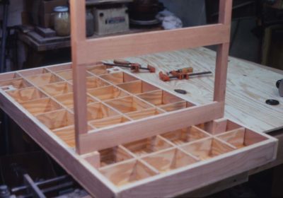
For this first final version I used the same structural strategy for the top, modifying the stock weight being the only real modification. On this second iteration I used 3/8″ A/C plywood for both the faces and ribs of the torsion box top rather than 1/4″ and 3/4″ luan for the same purpose on the prototype. Making the box approximately 3″ thick and placing the ribs in a 6″ x 6″ grid achieved a satisfactory result with essentially no change in weight while yielding a stout structure. In fact, I could do some pretty serious joinery and carving on the bench, which I couldn’t do with the prototype.
I wanted a large-capacity vise on my bench, but there was no point in defeating my original purpose by building a lightweight bench and then installing a heavy vise on it. The vise(s) I built opens about 12″ and employs aluminum threadstock for the screws, tapped holes in the endpiece of the top, and 2″ x 3″ x 24″ wood jaws. The screws pass through same-sized holes in the movable jaw, and terminate in simple wooden handles passing through holes drilled in the ends.
One pretty dramatic change in this function was to switch from standard steel threadstock to 1-inch aluminum rod stock that I had cut at a local machine shop (I already had the aluminum rod stock in my scrap barrel). It’s been a long time since this project but I recall paying $25 for the job. All it took was to set up the pieces in the lathe and cut the threads with a single pass, along with a single groove above the threads for some retaining collars. I’m guessing it took ten minutes maximum, so $25 for a quarter hour of machine shop time sounds about right. It might have been $25 for each pair of screws, but either way it seemed pretty reasonable.
My procedure for incorporating the vise into the bench top involved drilling oversized holes in the internal grid but not the added fixed jaw, so I couldn’t assemble the box all at once. I cut my grid pieces and glued them to one face of the torsion box using 315 gram hot hide glue, which was the adhesive employed throughout the project. After laying out for the vise screws, I drilled holes through the fixed jaw (the torsion box end pieces) to tap-out and received the threaded screws. I was unsure whether holes the same size as the aluminum rod stock used for the vise screws would be large enough to allow the screws to go through the grid members, given the inevitable wobble in the screws. To be on the safe side, I drilled larger holes through the grid to a slightly longer distance the desired vise opening dimension. The vise screws would then pass through these openings as the vise was closed. After I was sure the vise was fully operational, I glued the second face on the grid and the top was complete.
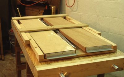
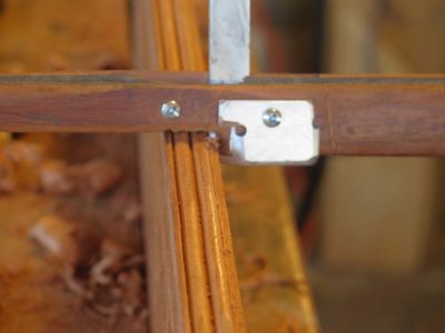
By fabricating simple leg end units with long folding diagonal braces, the problem of too much shimmying parallel to the long axis was overcome on the final bench. The leg units were fabricated from the clearest 2x construction lumber I could find, and the folding braces from 1/4″ x 1″ aluminum bar stock with 1″ x 1″ aluminum angle stock for the mounting brackets. The slightly heavier face plywood made it easy to screw all these elements to the underside.
The leg units were not installed symmetrical relative to the short axis, but rather were off-set by half the leg width so they could fold up next to each other rather than on top of each other. This way, the table could become a remarkably compact unit which needed absolutely no assembly or disassembly; it could just be folded up. Following final assembly I added a snap-on strap for carrying the bench like a large suitcase. By throwing the strap over my shoulder, I could easily carry the bench for long periods of time and maneuver it through pretty tight quarters.
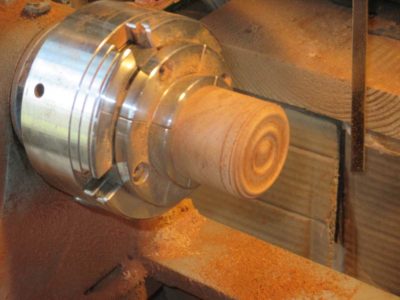
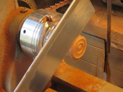
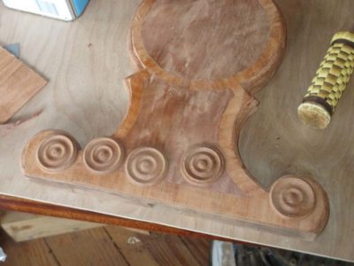
Though a minor piece of real estate on the desk, the roundels were certainly visually prominent. Thanks to my four-jaw chuck on the lathe making them was a breeze.
My first step was to make a cylinder from some of the mahogany then turn the roundel profile on the end of the cylinder. Once the profile was satisfactory I scored the lip of the roundel with a turning chisel then sawed off the circular wafer right on the lathe.
I repeated the process until I had excess roundels, then glued them in place.
In addition to the roundels there were bits of applied moldings to the field and bottom perimeter of the writing box and along the edges of the shelf. After spending numerous hours making the curved moldings on the legs these seemed like a holiday.
I simply cut the moldings on the edges of a board then ripped them off for application to the surface of the box.
The half-round string moldings in the field of the writing box allowed me to use a set of pinch clamps I’d made years before. These were featured in a Popular Woodworking article some time ago.
The only construction left to accomplish was to complete the top of the desk, then it would be on to the best part — finishing!
Sometimes you get lemon peels, sometimes you get lemon meringue pie.
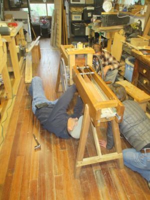
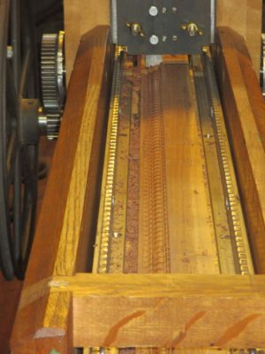
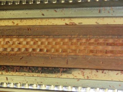
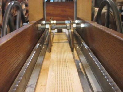
Thanks to a clearing on the calendar we’ll be convening the second Ripple Molding Soiree and Camp Out at The Barn the week of September 3. As before the agenda will be to explore the theoretical and practical aspects of making ripple moldings and their machines.
I think all of last year’s participants are coming, including at least one newly completed ripple molding machine in tow. For this year I know one of the participants is feverishly interested in making a bench top molding cutter to produce diminutive moldings and I am going to work on my prototype from last year and another Felibien-esque c.1675 model vaguely similar to the one we resurrected last year.
As before there will be no tuition fee, this is a mutual learning experience rather than a teaching/classroom event. We’ll share whatever material costs are incurred and pay for our own meals (normally for a workshop I provide or pay for the mid-day meal). If you are interested in participating feel free to drop me a line.
PS if this goes well my pal JohnH and I are hoping to teach a “Make A Ripple Molding Machine” workshop some time in 2019 and also make an instructional video on the same topic.
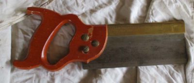
The rehabilitation of my first “brand name” dovetail saw began with dismantling all the components and re-thinking the proportional issues that rendered it an ill-fitted tool for me. As I said before, the cutting edge (teeth) of the saw was about the only thing I liked about it, so that would be left alone but everything else was on the table. Removing the handle was of course no more complicated than removing the saw nuts holding it on. (I’d already mucked around with the handle before I took this picture. Also, note the shallow bedding of the saw plate in the brass back).
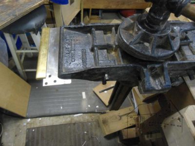
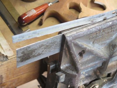
Separating the back and the plate was not much more involved. I set my Emmert vise to the horizontal position and tightened the saw plate in it. With a mallet and a stick I gently drove the back off the plate.
I addressed the easiest part first, the handle. I’ve been working wood for five decades but have not yet figure how to make holes smaller. Given that limitation I was stymied in making the handle and its way oversized hand-opening the right size for my hand, but at least I could make it more comfortable. I accomplished that by transforming it from a closed tote to an open tote, albeit a pretty ugly one. This did allow for and encourage a more comfortable grip on it and is an immense improvement. Still, I will make a whole new handle once I get a little ahead on the multitude of other projects occupying my days.
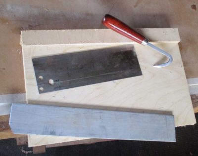
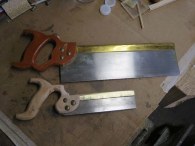
Next came the re-dimensioning of the saw plate which was just wa-a-ay to tall for my taste. Previously the distance from the teeth to the top of the spine was almost 3-1/2 inches, a pretty excessive proportion for an 8-inch saw. Some of this was due to how the plate was bedded in the back and some on the depth of the plate. The plate was a very hard piece of tool steel, probably cold-rolled sheet that was effectively forged and thus too hard to saw through. It was also too hard for my little sheet metal shear to cut through so I had to use a different approach.
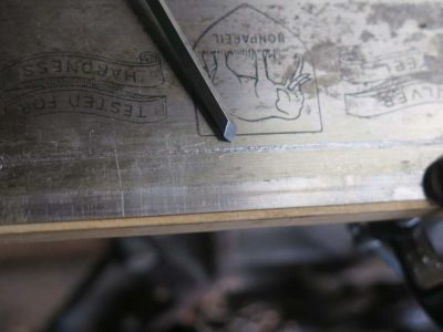
Instead I scored the plate with a scribe along the line I wanted to cut. I then used an engraving burin and took several passes along the scribed line to create a furrow, weakening the plate to the point where I could break off the excess. It worked like a charm.
I finished this slightly jagged edge with a diamond stone and it was ready to go back in action.
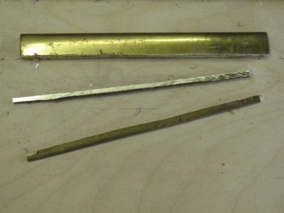
My final major modification was to narrow the brass spine. The saw was originally fitted with a bent back made from 1/8″ brass with a 1-1/8″ depth making it a stout, really heavy component. On a saw this small it threw the balance way off, another feature I did not like. I did not necessarily mind the depth of the back but it was just too massive as it was. Using a hacksaw I ripped a proud quarter inch from its depth, then finished the edge with a file resulting in a brass spine that is almost 1/3 lighter and narrower than it was before.
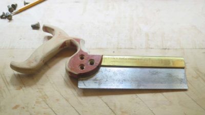
One final modification was to re-set the plate fully bedded into the bent back, as opposed to the original bedding that was only about 1/4″ at the tip of the back. The result of this combined with the cutting-down of the plate resulted in an 8-inch saw that was only about 2-1/4″ in overall depth versus the original 3-1/2″. This improvement alone was worth the effort as it makes the saw feel like more of an extension of my hand rather than some barnacle stuck there.
With all the old pieces made new, the reassembled saw more closely resembles a tool I might use regularly. The relatively heavy set for the teeth, at least when compared to my no-set tapered saw plate model, feels a little “wallow-y” in the kerf but performs well. I can definitely see this old/new saw becoming part of my regular repertoire of options.























Recent Comments